AIR CONDITIONING
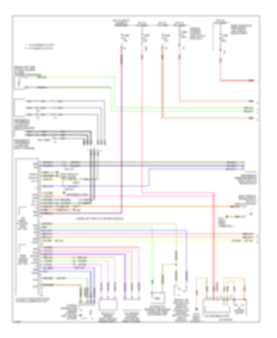
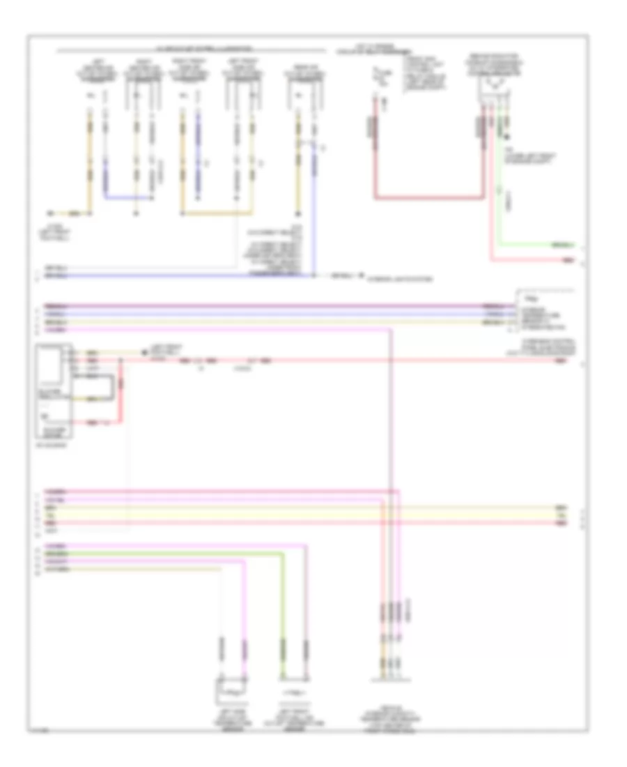
Automatic A/C Wiring Diagram, with Thermotronic (1 of 3) for Mercedes-Benz C250 2012
 https://portal-diagnostov.com/license.html
Automotive Electricians Portal FZCO
Automotive Electricians Portal FZCO
https://portal-diagnostov.com/license.html
https://portal-diagnostov.com/license.html
Automotive Electricians Portal FZCO
Automotive Electricians Portal FZCO
List of elements for Automatic A/C Wiring Diagram, with Thermotronic (1 of 3) for Mercedes-Benz C250 2012:
- (+)
- (behind left side of front bumper) outside temperature sensor
- (not used)
- (right rear of engine compt) coolant circulation pump
- (under left front of center console)
- 30g
- 34kd
- Ac housing
- Air quality sensor (right rear of engine compt)
- Air recir- culation mode button
- Automatic air conditioning control & operating unit
- Bf-sig
- Blower motor
- Blower regulator
- Can-b h
- Can-b l
- Central air distribution position detection microswitch (comfort) (bottom right side of hvac unit)
- Computer data lines system
- Defogger system
- Evaporator temperature sensor (lower left side of evaporator)
- F-sig
- Front electrical prefuse box (left side of engine compt)
- Fuse 10a
- Fuse 150a
- Fuse 40a
- Fuse 7.5a
- Fuse 80a
- Gnd
- Hot at all times
- Hot w/ circuit 30g relay energized
- In-b8
- Interior temperature sensor (comfort) (left center of dash)
- Lin b8
- Mk (+)
- Mot
- Nca
- Rear window heater button
- Red
- Refrigerant compressor (lower left front of engine)
- Refrigerant pressure sensor (right front of engine compt)
- Rv (+)
- Rv (-)
- S-sig
- S29
- Sig
- Sun sensor (comfort) (top center front of dash)
- Vehicle interior fuse box (right front footwell)
- W/ magnetic clutch
- W/o magnetic clutch
- W12
- W15/1 (right front footwell)
- W3/1 (right front wheelwell)
- X25/14-c1
- X26-c1
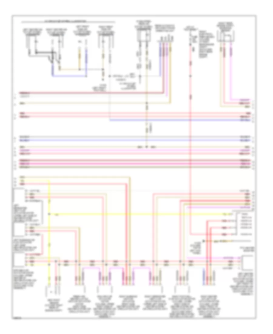
Automatic A/C Wiring Diagram, with Thermotronic (2 of 3) for Mercedes-Benz C250 2012
 https://portal-diagnostov.com/license.html
Automotive Electricians Portal FZCO
Automotive Electricians Portal FZCO
https://portal-diagnostov.com/license.html
https://portal-diagnostov.com/license.html
Automotive Electricians Portal FZCO
Automotive Electricians Portal FZCOList of elements for Automatic A/C Wiring Diagram, with Thermotronic (2 of 3) for Mercedes-Benz C250 2012:
- (if equipped) rear air outlet symbol illumination
- (right rear engine compt) emissions sensor
- 12v
- 58d
- Data
- Dew point sensor (c-class: right rear of engine compt)
- Diffuse flap actuator motor (c-class: upper center of heater system air circulation unit) (glk-class: hvac assembly)
- Fresh air/ recirculation air flap actuator motor (right side heater system air circulation unit)
- Front electrical prefuse box (c-class: at right rear engine compt) (glk-class: right rear engine compt)
- Fuse 150a
- Gnd
- Hot at all times
- Left blending air flap actuator (left side heater system air circulation unit)
- Left center air outlet symbol illumination
- Left center outlet flap actuator motor (c-class: lower left front of heater system air circulation unit) (glk-class: hvac assembly)
- Left defroster vent flap actuator motor (upper left side of heater system air circulation unit)
- Left front side air outlet symbol illumination
- Mr6
- Nca
- Ptc heater booster
- Ram air flap actuator motor (c-class: upper right side of heater system air circulation unit) (glk-class: hvac assembly)
- Rear automatic air conditioning operating unit
- Red
- Right blending air flap actuator (right side heater system air circulation unit)
- Right center air outlet symbol illumination
- Right center outlet flap actuator motor (c-class: lower right front of heater system air circulation unit) (glk-class: hvac assembly)
- Right defroster vent flap actuator motor (upper left side of heater system air circulation unit)
- Right footwell flap actuator motor (c-class: lower right side of heater system air circulation unit) (glk-class: right side heater system air circulation unit
- Right front side air outlet symbol illumination
- W/ air outlet symbol illumination
- W15/5 (left front footwell)
- W15/9 (c-class: top of left kick panel)
- X18/35-c1
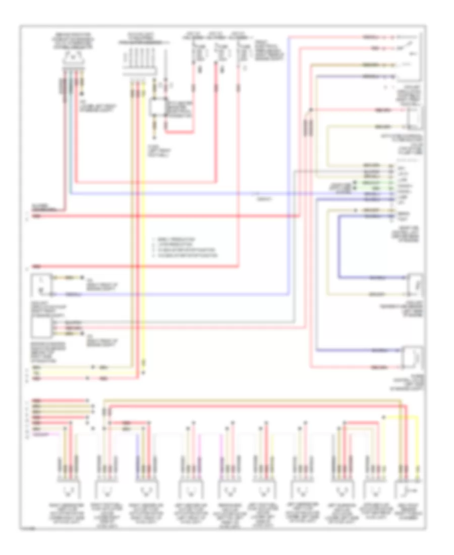
Automatic A/C Wiring Diagram, with Thermotronic (3 of 3) for Mercedes-Benz C250 2012
 https://portal-diagnostov.com/license.html
Automotive Electricians Portal FZCO
Automotive Electricians Portal FZCO
https://portal-diagnostov.com/license.html
https://portal-diagnostov.com/license.html
Automotive Electricians Portal FZCO
Automotive Electricians Portal FZCOList of elements for Automatic A/C Wiring Diagram, with Thermotronic (3 of 3) for Mercedes-Benz C250 2012:
- (behind radiator) combustion engine & a/c w/ integrated control fan motor
- (in hvac unit) (if equipped) ptc heater booster
- (right rear of
- Activated charcoal filter shutoff valve (top of fuel filler tube)
- Akv
- Can-e h
- Can-e l
- Computer data lines system
- Coolant circulation pump (right front of engine compt)
- Coolant circulation pump relay (right front footwell)
- Coolant temperature sensor (left rear of engine)
- Dew point sensor (right plenum chamber)
- Diffuse flap actuator motor (top center of hvac unit)
- Early production
- Engine compt)
- Engine diagnosis radiator sensor (behind top right side of radiator)
- Front electrical prefuse box
- Fuse 100a
- Fuse 150a
- Fuse 50a
- Hot at all times
- Late production
- Left blending air flap actuator (lower left side of hvac unit)
- Left center air outlet flap actuator motor (left front of hvac unit)
- Left defroster vent flap actuator motor (upper left side of hvac unit)
- Left footwell flap actuator motor (lower left side of hvac unit)
- Lin c1
- Llkr
- Lpv
- Lues
- Me-sfi (me) control unit (center rear of engine)
- Mr4
- Mr5
- Ptc heater booster electrical connector
- Purge control valve (left side of engine compt)
- Rear blend air flap actuator motor (bottom left front of hvac unit)
- Red
- Right center air outlet flap actuator motor (right front of hvac unit)
- Right defroster vent flap actuator motor (upper right side of hvac unit)
- Right footwell flap actuator motor (lower right side of hvac unit)
- Senm3
- Tmot
- W/ eco start/stop function
- W/o eco start/stop function
- W15/5 (left front footwell)
- W2 (right front of engine compt)
- W9 (lower left front of engine compt)
- X25/2-c1
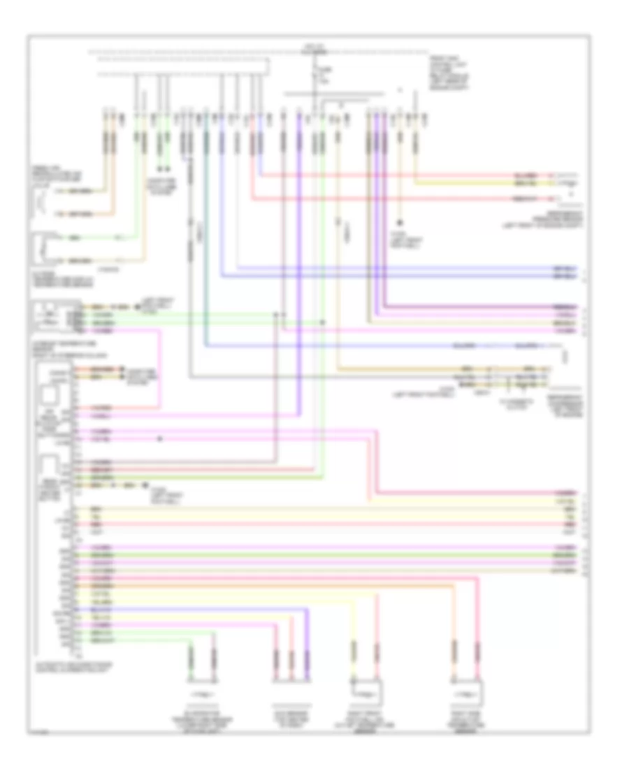
Automatic A/C Wiring Diagram, without Thermotronic (1 of 2) for Mercedes-Benz C250 2012
 https://portal-diagnostov.com/license.html
Automotive Electricians Portal FZCO
Automotive Electricians Portal FZCO
https://portal-diagnostov.com/license.html
https://portal-diagnostov.com/license.html
Automotive Electricians Portal FZCO
Automotive Electricians Portal FZCOList of elements for Automatic A/C Wiring Diagram, without Thermotronic (1 of 2) for Mercedes-Benz C250 2012:
- (left front footwell) w15/5
- 12v
- 30g
- Air recir- culation mode button
- Automatic air conditioning control & operating unit
- C13d
- C14m
- C17c
- C18m
- C19i
- C20m
- C21m
- C3m
- C5c
- Can-b h
- Can-b l
- Computer data lines system
- Evaporator temperature sensor (lower right side of hvac unit)
- Fresh air/ recirculated air flap switchover valve
- Front sam control unit w/ fuse/ relay module (left rear of engine compt)
- Fuse 7.5a
- Gnd
- Hot at all times
- Interior temperature sensor (right of steering column)
- Lin b8
- Outside temperature display temperature sensor
- Rear window heater button
- Red
- Refrigerant compressor (left front of engine)
- Refrigerant pressure sensor (left front of engine compt)
- Right front footwell air outlet temperature sensor
- Right side air outlet temperature sensor
- Sig
- Sig li
- Sig re
- State solid
- Sun sensor (top center of dash)
- W/ magnetic clutch
- W15/2 (left front footwell)
- W15/5 (left front footwell)
- X15/5-c2
- X25/2-c1
- X26-c1
Automatic A/C Wiring Diagram, without Thermotronic (2 of 2) for Mercedes-Benz C250 2012
 https://portal-diagnostov.com/license.html
Automotive Electricians Portal FZCO
Automotive Electricians Portal FZCO
https://portal-diagnostov.com/license.html
https://portal-diagnostov.com/license.html
Automotive Electricians Portal FZCO
Automotive Electricians Portal FZCOList of elements for Automatic A/C Wiring Diagram, without Thermotronic (2 of 2) for Mercedes-Benz C250 2012:
- (behind radiator) combustion engine & a/c w/ integrated control fan motor
- (left front footwell) w15/5
- Ac housing
- Blower motor
- Blower regulator
- C14m
- Front sam control unit w/ fuse & relay module (left rear of engine compt)
- Fuse 15a
- Hot w/ engine circuit 87 relay energized
- Interior lights system
- Interior temperature sensor w/ integrated fan
- Left center air outlet symbol illumination
- Left front footwell air outlet temperature sensor
- Left front side air outlet symbol illumination
- Left side air outlet temperature sensor
- Overhead control panel electronics (w/o titling/sliding roof)
- Rear air outlet symbol illumination
- Red
- Right center air outlet symbol illumination
- Right front side air outlet symbol illumination
- Vehicle interior humidity/ temperature sensor (top center of front windshield)
- W/ air outlet symbol illumination
- W15/5 (left front footwell)
- W18 (w/o direct select) w19 (w/ direct select) (w/o direct select: under driver's seat) (w/ direct select: under front passenger's seat)
- W9 (lower left front of engine compt)
- X157/1-c2
- X18-c4
- X25/2-c1
- X83/11-c2

 Čeština
 Dansk
Dansk Deutsch
 Ελληνικά
 English
 English
 Español
 Suomi
Suomi Français
 Français
 Hrvatski
 Magyar
 Italiano
 日本語
日本語 한국어
한국어 Nederlands
 Polski
 Português
 Português
 Română
 Русский
 Slovenčina
 Slovenščina
 Svenska
 Türkçe
 中文 (中国)
