HORN
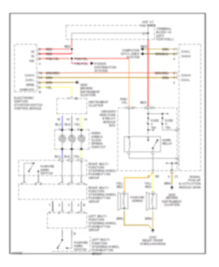
Horn Wiring Diagram for Mercedes-Benz E320 4Matic 2000
 https://portal-diagnostov.com/license.html
Automotive Electricians Portal FZCO
Automotive Electricians Portal FZCO
https://portal-diagnostov.com/license.html
https://portal-diagnostov.com/license.html
Automotive Electricians Portal FZCO
Automotive Electricians Portal FZCO
List of elements for Horn Wiring Diagram for Mercedes-Benz E320 4Matic 2000:
- 15r
- 2.1
- Can h
- Can l
- Computer data lines system
- Driver's side fuse & relay module box
- Electronic ignition- starter switch control module
- Fanfare horn switch
- Fanfare horns
- Fuse 10a
- Fuse 15a
- G101 (right front wheelhousing)
- G202 (behind
- G202 (behind instrument cluster)
- Horn relay
- Horn sw
- Horn/ airbag clock spring contact
- Hot at all times
- Instrument cluster
- Instrument cluster)
- Left multi- function steering wheel pushbutton group
- Power distribution system
- Red
- Right multi- function steering wheel pushbutton group
- Signal pick-up & activation module (sam)
- Terminal block x4 (left footwell)
 Čeština
 Dansk
Dansk Deutsch
 Ελληνικά
 English
 English
 Español
 Suomi
Suomi Français
 Français
 Hrvatski
 Magyar
 Italiano
 日本語
日本語 한국어
한국어 Nederlands
 Polski
 Português
 Português
 Română
 Русский
 Slovenčina
 Slovenščina
 Svenska
 Türkçe
 中文 (中国)
 עברית
עברית
