ENGINE PERFORMANCE
3.2L
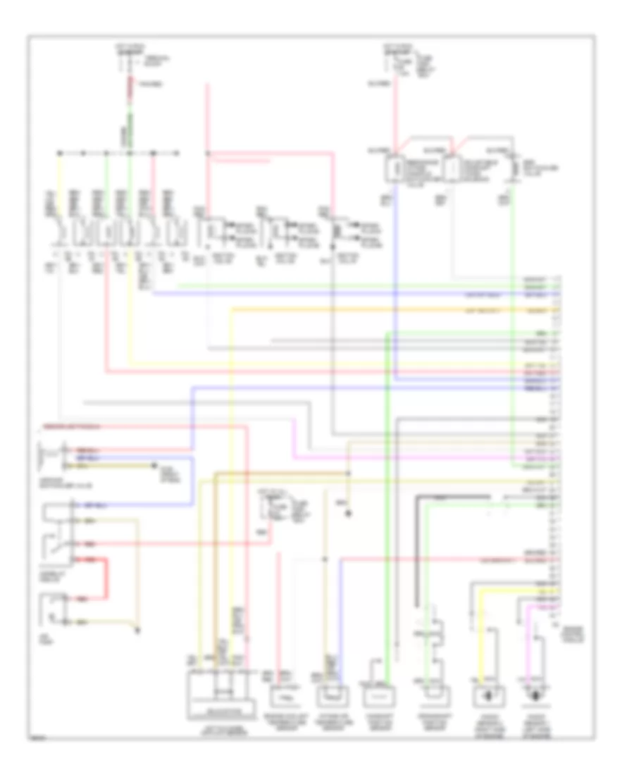
3.2L, Engine Performance Wiring Diagrams (1 of 2) for Mercedes-Benz SL320 1996

List of elements for 3.2L, Engine Performance Wiring Diagrams (1 of 2) for Mercedes-Benz SL320 1996:
- (behind right rear seat)
- (center console)
- 30a
- 4d2
- Acc
- Base module
- Battery
- Check engine light
- Data link connector (dtc readout) (in right component compt.)
- Diagnostic module ii
- Electronic accelerator/ cruise control/ idle speed control module or cruise control/ idle speed control module
- Engine control module (hfm-sfi)
- Fuel pump assembly
- Fuel pump relay module
- Fuse 7.5a
- Fuse and relay box
- G301 (below right front seat)
- G302
- G310
- Hot at all times
- Hot in run or start
- Ignition switch
- Instru- ment cluster system
- Instrument cluster
- Instrument cluster system
- Lock
- Nca
- O2s 1
- O2s 2
- O2s 2 heater relay module
- P/n
- Purge control valve
- Red
- Run
- Start
- Starter
- Starter lock-out/ backup lamp switch
- Terminal block
- Transmission control module
- Transmission overload protection switch
- Upshift delay switch- over valve
- W/ elect accel w/o elect accel
3.2L, Engine Performance Wiring Diagrams (2 of 2) for Mercedes-Benz SL320 1996
List of elements for 3.2L, Engine Performance Wiring Diagrams (2 of 2) for Mercedes-Benz SL320 1996:
- (left side
- (right side
- Adjustable camshaft timing solenoid
- Air pump
- Air pump switchover valve
- Air relay module
- Camshaft position sensor
- Crankshaft position sensor
- Egr switchover valve
- Engine control module
- Engine coolant temperature sensor
- Fuse 7.5a
- Fuse and relay box
- Fuse m4 40a
- G125 (front of eng)
- Hot at all times
- Hot film mass air flow sensor
- Hot in run or start
- Ignition coil #1
- Ignition coil #2
- Ignition coil #3
- Inj. #1
- Inj. #2
- Inj. #3
- Inj. #4
- Inj. #5
- Inj. #6
- Intake air temperature sensor
- Knock
- Nca
- Of engine)
- Pnk/ red
- Pnk/red
- Red
- Resonance intake manifold switchover valve
- Sensor 1
- Sensor 2
- Solid state
- Spark plug #1
- Spark plug #2
- Spark plug #3
- Spark plug #4
- Spark plug #5
- Spark plug #6
- Terminal block
TRANSMISSION
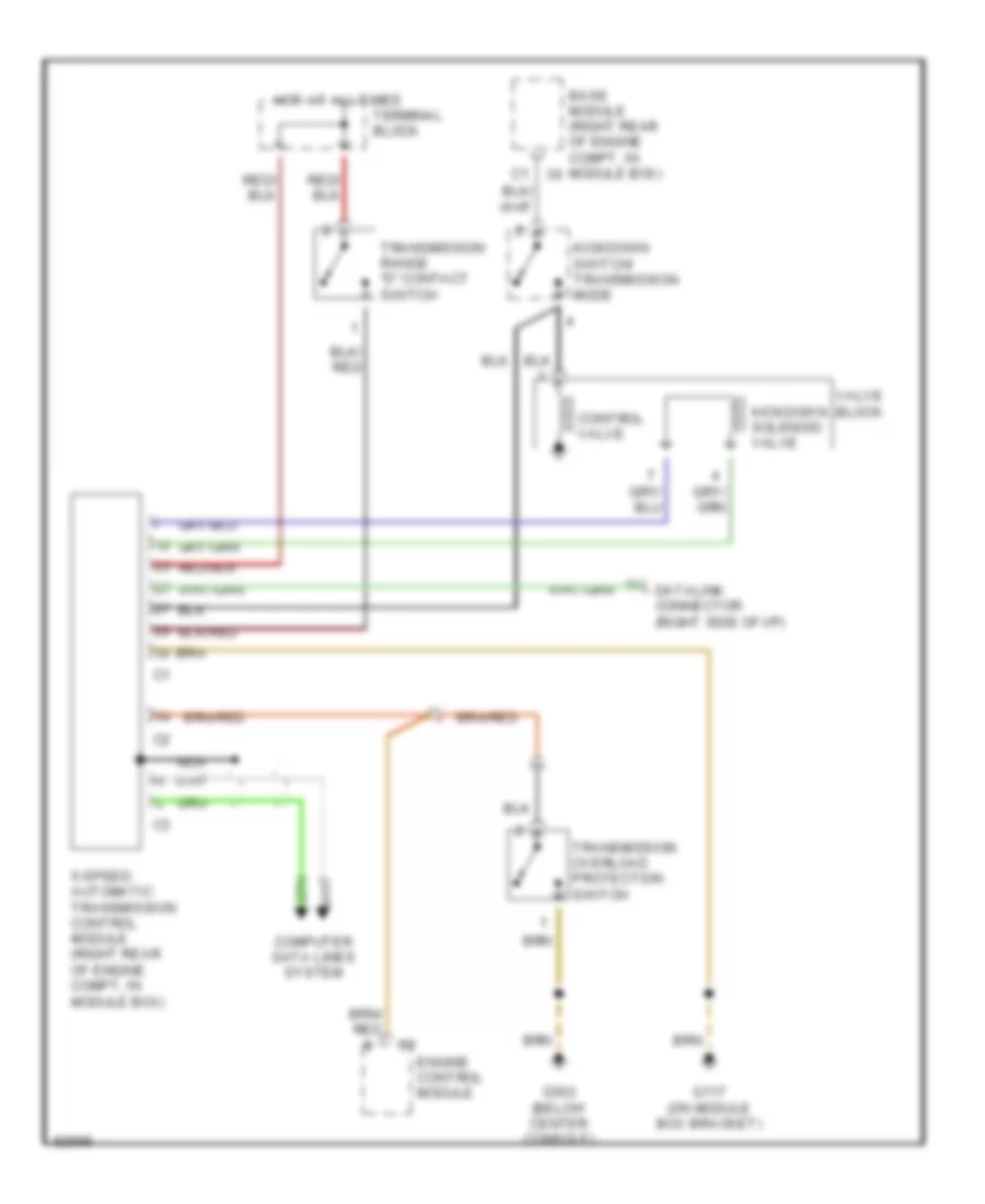
Transmission Wiring Diagram for Mercedes-Benz SL320 1996
List of elements for Transmission Wiring Diagram for Mercedes-Benz SL320 1996:
- 5-speed automatic transmission control module (right rear of engine compt, in module box)
- Base module (right rear of engine compt, in module box)
- Computer data lines system
- Control valve
- Datalink connector (right sdie of i/p)
- Engine control module
- G117 (on module box bracket)
- G302 (below center console)
- Hot at all times
- Kickdown solenoid valve
- Kickdown switch/ transmission mode
- Nca
- Terminal block
- Transmission overload protection switch
- Transmission range "d" contact switch
- Valve block