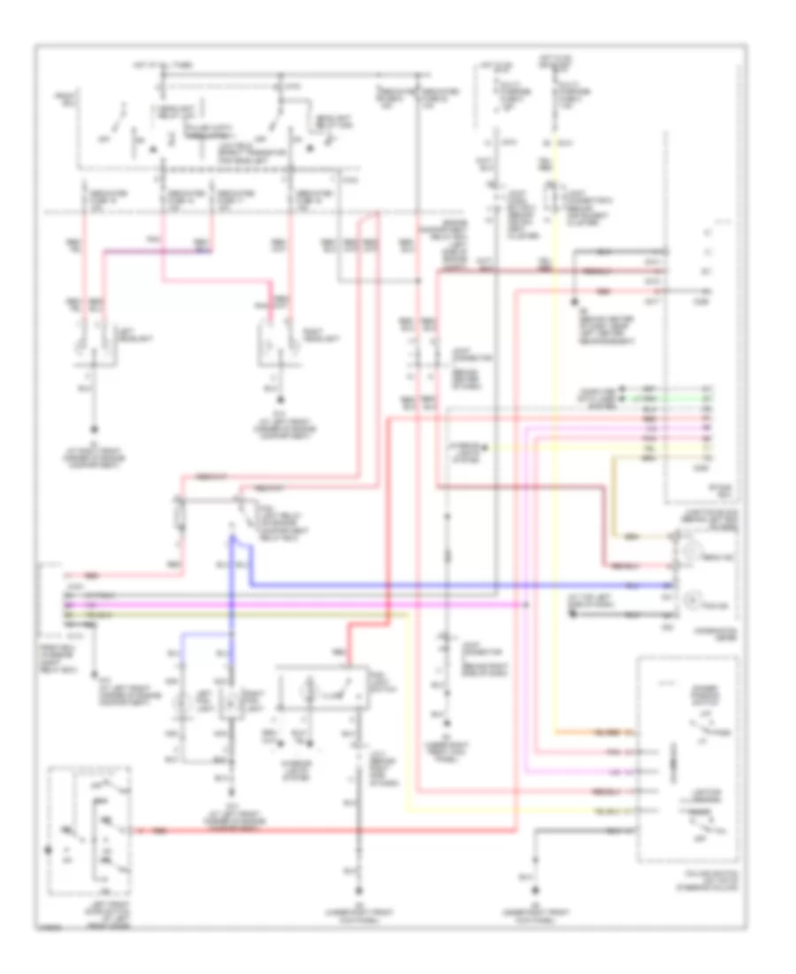
HEADLIGHTS
Headlights Wiring Diagram for Mitsubishi Lancer ES 2007
List of elements for Headlights Wiring Diagram for Mitsubishi Lancer ES 2007:
- (at left front corner of engine compartment)
- (at top left side of dash) g7
- (behind instrument cluster)
- A10x
- A11x
- Beam ind
- C01
- C02
- C210
- C214
- C217
- C226
- C228
- Column switch (on top of steering column)
- Column-ecu
- Combination meter
- Computer data lines system
- Dedicated fuse 16 10a
- Dedicated fuse 17 10a
- Dedicated fuse 18 10a
- Dedicated fuse 19 10a
- Dedicated fuse 22 10a
- Dedicated fuse 6 15a
- Dimmer/ passing switch
- Engine compartment relay box (left side of engine compt)
- Etacs ecu
- Fog ind
- Fog light relay (on engine compartment relay box)
- Fog- light switch
- Front ecu
- Front-ecu (in engine compt relay box)
- G1 (at right front corner of engine compartment)
- G13
- G3 (under right front kick panel)
- G6 (behind center of dash, near left center reinforcement)
- Head
- Headlight relay high
- Headlight relay low
- Hot at all times
- Hot in on
- Hot in on or start
- Illum
- Interior lights system
- J/c 3 (behind right side of dash)
- Joint conn- ector 2 (behind instru- ment cluster)
- Joint connector (behind center of dash)
- Joint connector (behind right side of dash)
- Joint connector 5
- Junction block (behind left end of dash)
- Left fog- light
- Left front door switch (at left front door)
- Left headlight
- Lighting switch
- Low field effect transistor for headlight
- Multi- purpose fuse 2 7.5a
- Multi- purpose fuse 5 7.5a
- Nca
- Off
- Pass
- Pnk
- Pulse width modulation
- Red
- Right fog- light
- Right headlight
- Tail
 English