HEADLIGHTS
Headlights Wiring Diagram, with High Intensity Discharge (1 of 2) for Mitsubishi Lancer GT 2012

List of elements for Headlights Wiring Diagram, with High Intensity Discharge (1 of 2) for Mitsubishi Lancer GT 2012:
- (behind right kick panel) g4
- (right of accelerator pedal) (evolution) g5
- A-39
- A-50
- Anti-theft system
- Beam ind
- C-130
- C-133
- C-22
- C-23
- C-301
- C-304
- C-312
- C-316
- C-317
- Can drive circuit
- Can transceiver circuit
- Circuit
- Circuit headlight backup
- Circuit lin drive
- Combination meter
- Computer data lines system
- Cpu
- Daytime running light relay (on underhood fuse/relay block)
- Engine compartment fuse/relay box (left side of engine compt)
- Etacs-ecu (on rear of junction block, behind left end of dash)
- Evolu- tion
- Evolution
- Except evolution
- Exterior lights system
- Fog ind
- Fog light relay
- Fuse 10a
- Fuse 15a
- Fuse 7.5a
- G1 (at right front corner of engine compt)
- G13 (except evolution) (behind left side of dash)
- G7 (except evolution) (top left side of headliner)
- G8 (evolution)
- Hot at all times
- Hot w/ ig1 relay energized
- Ignition control
- Interface circuit
- J/c c-03 (except evolution) (2.0l & 2.4l: (right side of dash) j/c c-101 (evolution)
- Led drive circuit
- Left drl headlight assembly
- Left fog light
- Lighting control sensor (w/ automatic light) (center top of windshield)
- Nca
- Parking brake switch (under center console)
- Pnk
- Red
- Right drl headlight assembly
- Right fog light
- Taillight control
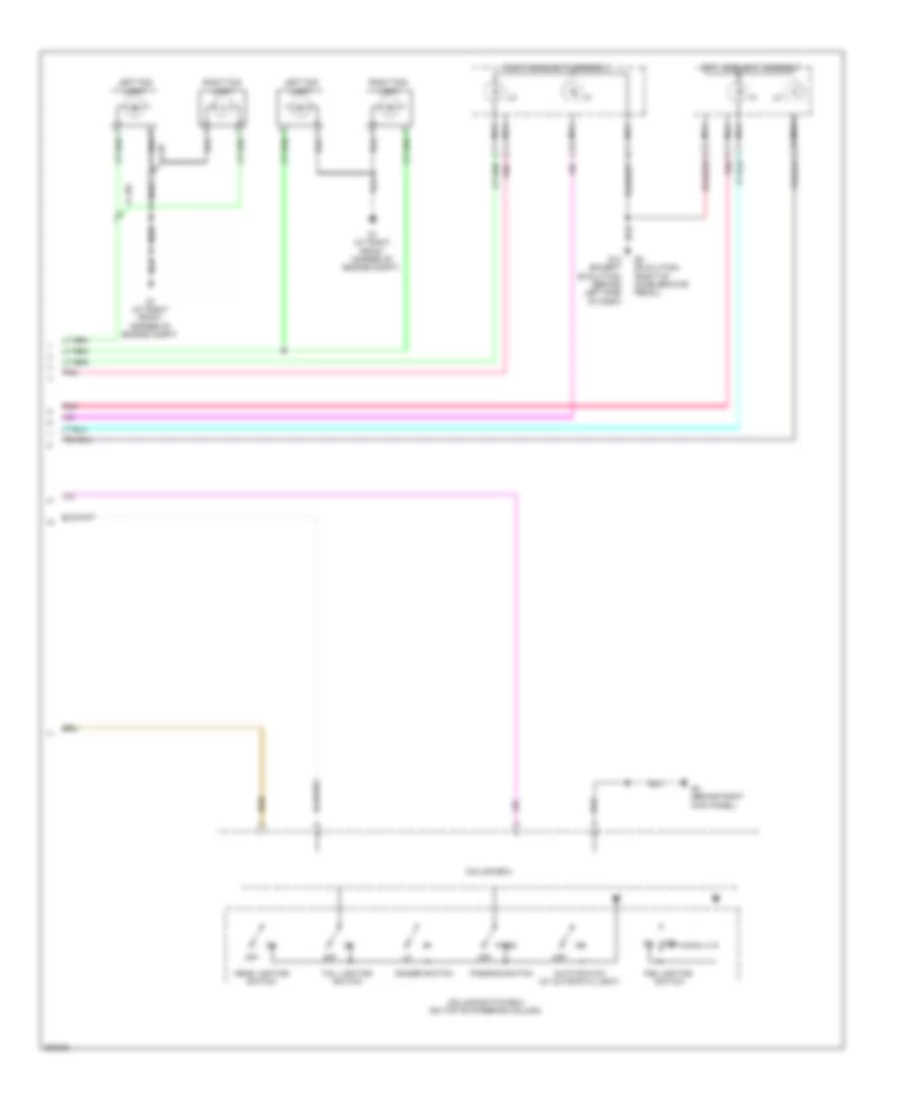
Headlights Wiring Diagram, with High Intensity Discharge (2 of 2) for Mitsubishi Lancer GT 2012
List of elements for Headlights Wiring Diagram, with High Intensity Discharge (2 of 2) for Mitsubishi Lancer GT 2012:
- Auto switch (w/ automatic light)
- Column switch-ecu (on top of steering column)
- Column-ecu
- Dimmer switch
- Engine compartment fuse/relay box (left side of engine compt)
- Fog lighting switch
- Fuse 10a
- Fuse 20a
- Fusible link 36 120a
- Fusible link box (next to battery)
- G1 (at right front corner of engine compt)
- G4 (behind right kick panel)
- Head lighting switch
- Headlight control unit
- Headlight relay (high)
- Headlight relay (low)
- Hot at all times
- Left fog light
- Left headlight assembly
- Nca
- Off
- Pass
- Passing switch
- Right fog light
- Right headlight assembly
- Solenoid
- Tail lighting switch
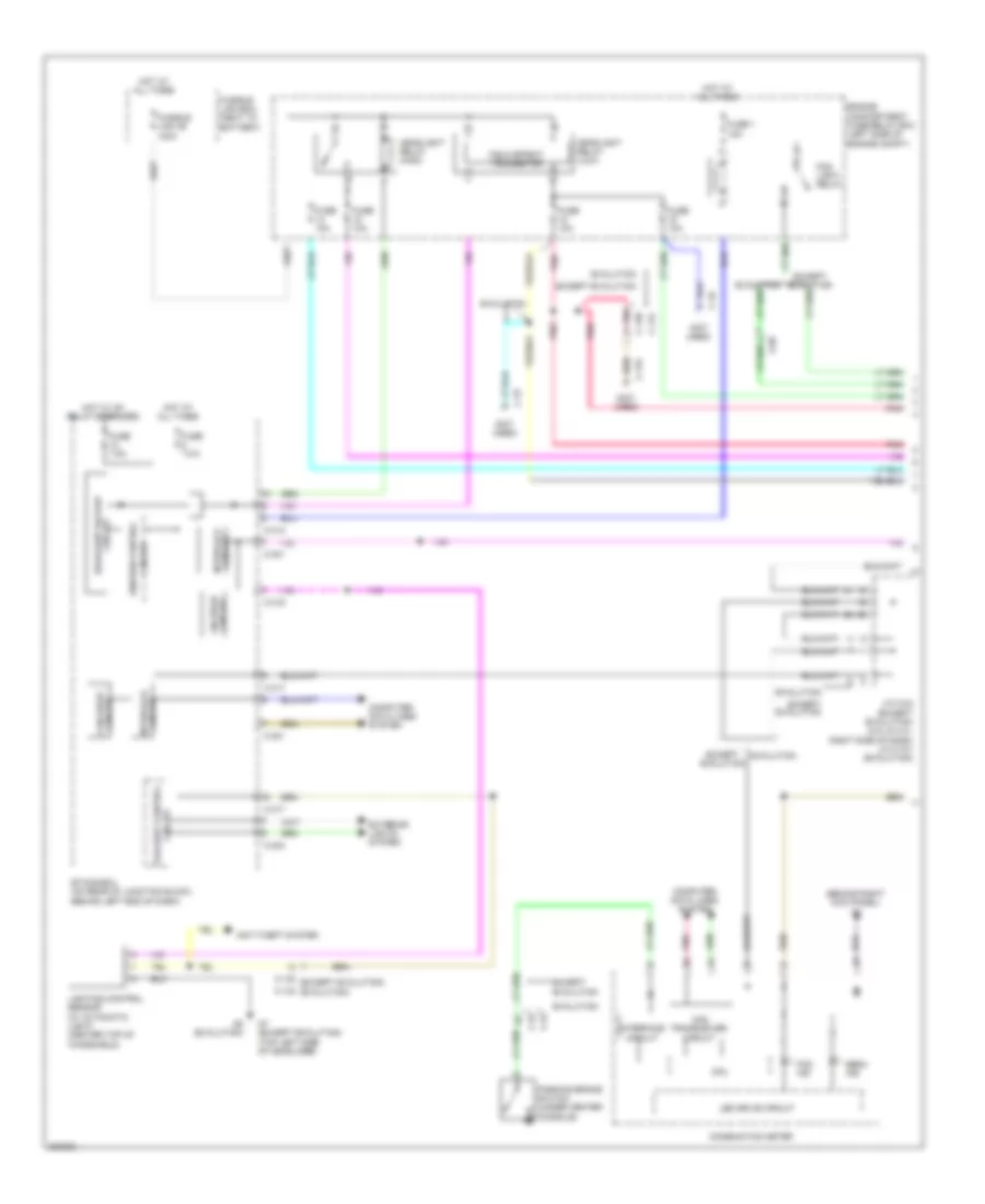
Headlights Wiring Diagram, without High Intensity Discharge (1 of 2) for Mitsubishi Lancer GT 2012
List of elements for Headlights Wiring Diagram, without High Intensity Discharge (1 of 2) for Mitsubishi Lancer GT 2012:
- (behind right kick panel) g4
- (not used)
- A-50
- Anti-theft system
- Beam ind
- C-128
- C-130 (except evolution)
- C-131
- C-133 (evolution)
- C-134
- C-19
- C-22
- C-23
- C-301
- C-304
- C-312
- C-316
- C-317
- Can transceiver circuit
- Circuit
- Circuit can drive
- Circuit headlight backup
- Circuit interface
- Combination meter
- Computer data lines system
- Cpu
- Engine compartment fuse/relay box (left side of engine compt)
- Etacs-ecu (on rear of junction block, behind left end of dash)
- Evolution
- Except evolution
- Exterior lights system
- Field effect transistor
- Fog ind
- Fog light relay
- Fuse 1 15a
- Fuse 10a
- Fuse 7.5a
- Fusible link 36 120a
- Fusible link box (next to battery)
- G7 (except evolution) (top left side of headliner)
- G8 (evolution)
- Headlight relay (high)
- Headlight relay (low)
- Hot at all times
- Hot w/ ig1 relay energized
- Ignition control
- Interface circuit
- J/c c-03 (except evolution) (2.0l & 2.4l: right side of dash) j/c c-101 (evolution)
- Led drive circuit
- Lighting control sensor (w/ automatic light) (center top of windshield)
- Lin drive circuit
- Parking brake switch (under center console)
- Pnk
- Taillight control
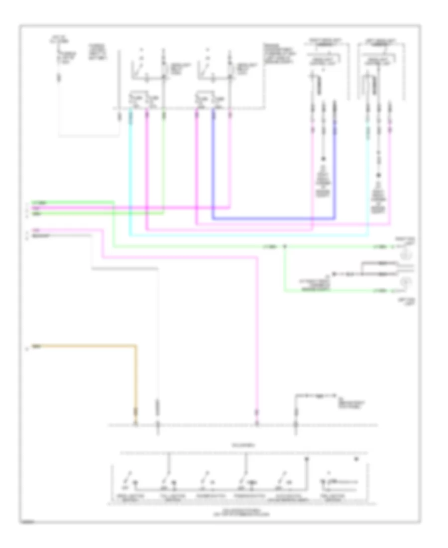
Headlights Wiring Diagram, without High Intensity Discharge (2 of 2) for Mitsubishi Lancer GT 2012
List of elements for Headlights Wiring Diagram, without High Intensity Discharge (2 of 2) for Mitsubishi Lancer GT 2012:
- A-139
- A-39
- Auto switch (w/ automatic light)
- Column switch-ecu (on top of steering column)
- Column-ecu
- Dimmer switch
- Fog lighting switch
- G1 (at right front corner of engine compt)
- G13 (except evolution) (behind left side of dash)
- G4 (behind right kick panel)
- G5 (evolution) (right of accelerator pedal)
- Head lighting switch
- Left fog light
- Left headlight assembly
- Nca
- Off
- Pass
- Passing switch
- Pnk
- Right fog light
- Right headlight assembly
- Tail lighting switch