HEADLIGHTS
Headlights Wiring Diagram, Evolution for Mitsubishi Lancer O-Z Rally 2005

List of elements for Headlights Wiring Diagram, Evolution for Mitsubishi Lancer O-Z Rally 2005:
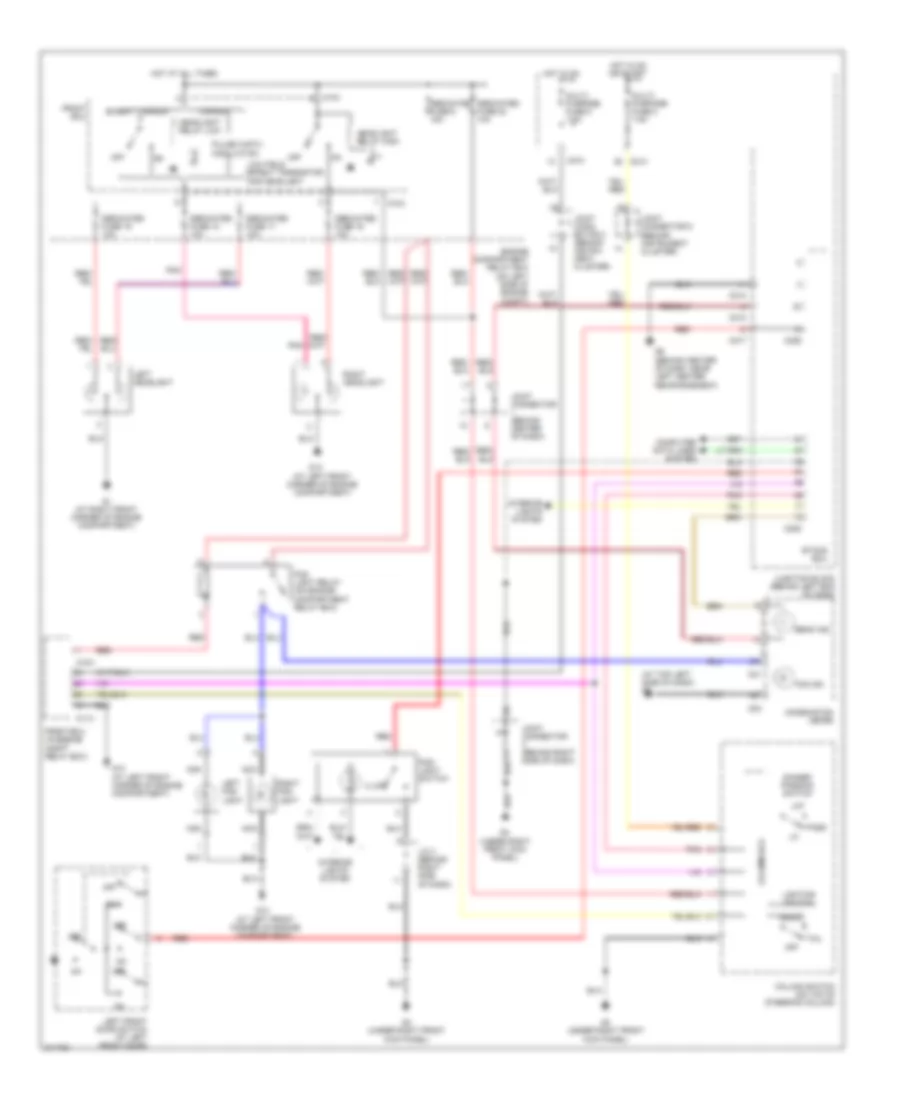
Headlights Wiring Diagram, Except Evolution for Mitsubishi Lancer O-Z Rally 2005
List of elements for Headlights Wiring Diagram, Except Evolution for Mitsubishi Lancer O-Z Rally 2005: