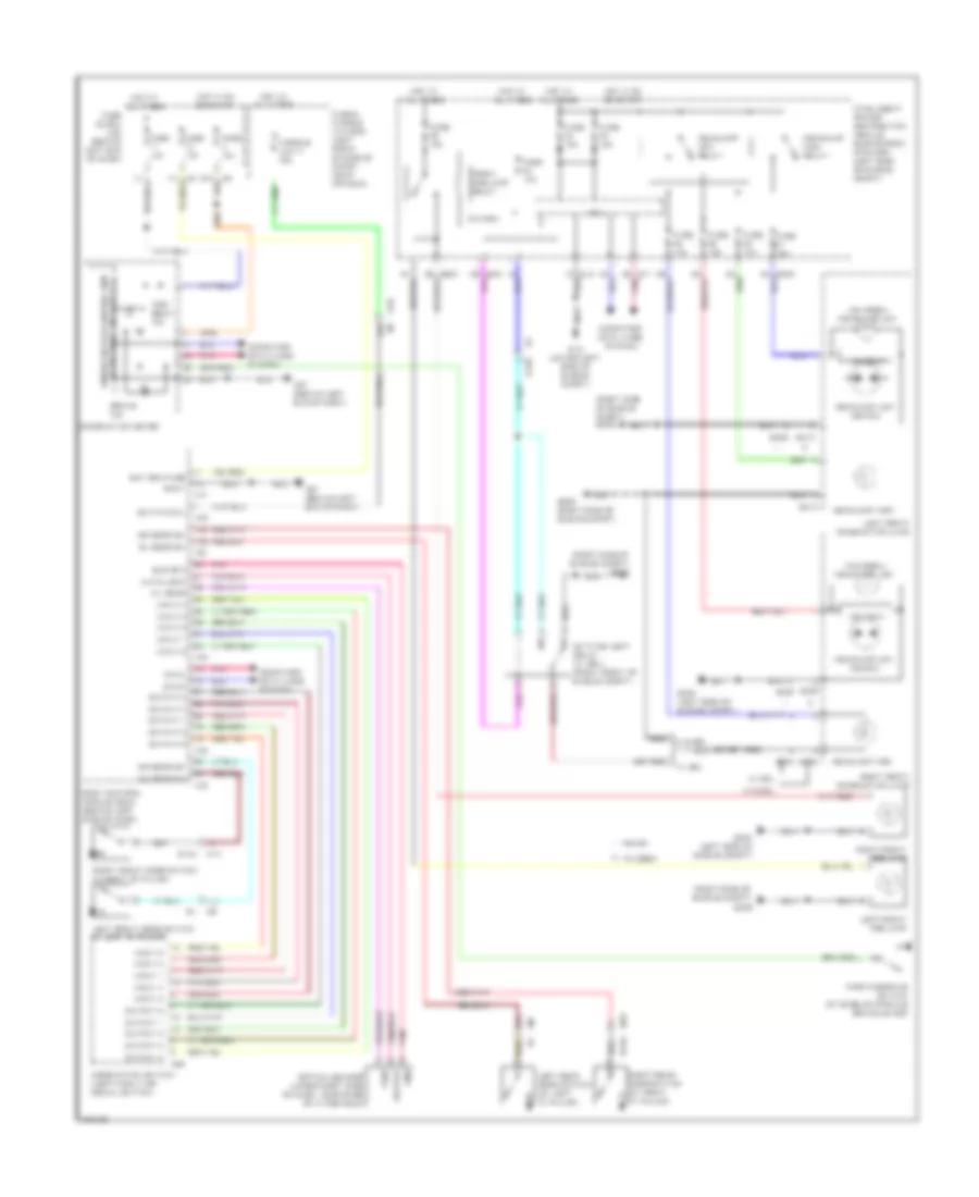
HEADLIGHTS
Headlights Wiring Diagram for Nissan Altima 2012
List of elements for Headlights Wiring Diagram for Nissan Altima 2012:
- (halogen) headlamp low
- (right side of engine compt)
- (right side of engine compt) e209
- 17j
- 22j
- 82g
- A/l sens
- As door sw
- Auto light
- B104
- Bat bcm fuse
- Bat pwr f/l
- Body control module (bcm) (behind left side of dash)
- Brake ind
- Can-h
- Can-l
- Canada
- Combination meter
- Combination switch (lighting & turn signal switch)
- Computer data lines system
- Cpu
- Daytime light relay (w/ drl) (right front of engine compt)
- Dr door sw
- E15 (lower left side of engine compt)
- E17 pnk
- E18
- E200
- E202
- E204 (left side of engine compt)
- E209
- E209 (right side of engine compt)
- E212
- E213
- E222
- E223
- E232
- E242
- E243
- E30
- Front fog lamp relay
- Fuse & fusible link box (left front of engine compt, near ipdm e/r)
- Fuse 10a
- Fuse 15a
- Fuse block (j/b) (behind left end of dash)
- Fusible link h 40a
- Gnd
- Gnd 1
- Gnd rf 2
- Halogen
- Headlamp high
- Headlamp high relay
- Headlamp low (xenon)
- Headlamp low relay
- Hid cont
- High beam ind
- Hot at all times
- Hot in on or start
- Input 1
- Input 2
- Input 3
- Input 4
- Input 5
- Intelligent power distribution module engine room (ipdm e/r) (left side of engine compt)
- Left front combination lamp
- Left front door switch (in left "b" pillar)
- Left front fog lamp
- Left rear door switch (at left "c" pillar)
- M10
- M16
- M17
- M18
- M19
- M21
- M28
- M57 (behind left end of dash)
- Optical sensor (upper right side of dash, near base of windshield)
- Output
- Output 1
- Output 2
- Output 3
- Output 4
- Output 5
- Parking brake switch (at base of parking brake lever)
- Pnk
- Pwr
- Right front combination lamp
- Right front door switch (in right "b" pillar)
- Right front fog lamp
- Right rear door switch (at right "c" pillar)
- Rl door sw
- Rr door sw
- Unified meter control unit (w/ information display)
- W/ drl
- W/o drl
- Xenon
 English