
HORN
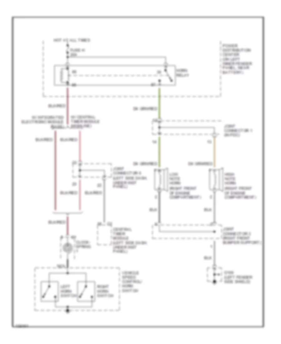
Horn Wiring Diagram for Dodge Cab & Chassis R2500 2001
List of elements for Horn Wiring Diagram for Dodge Cab & Chassis R2500 2001:
AIR CONDITIONINGBODY COMPUTERANTI-LOCK BRAKESCRUISE CONTROLCOMPUTER DATA LINESANTI-THEFTGROUND DISTRIBUTIONDEFOGGERSHEADLIGHTSENGINE PERFORMANCEEXTERIOR LIGHTSPOWER SEATSINSTRUMENT CLUSTERHORNPOWER WINDOWSINTERIOR LIGHTSPOWER DISTRIBUTIONPOWER MIRRORSPOWER DOOR LOCKSRADIOSUPPLEMENTAL RESTRAINTSSTARTING/CHARGINGTRANSMISSIONWARNING SYSTEMSWIPER/WASHER