HORN
Horn Wiring Diagram, with Stripped Chassis for Ford E-350 Super Duty XLT 2014

List of elements for Horn Wiring Diagram, with Stripped Chassis for Ford E-350 Super Duty XLT 2014:
- 20a
- Battery junction box (bjb) (mounted to front of left chassis frame rail)
- C218b
- C218c
- C291
- Clockspring (steering wheel)
- Fuse 34
- G101 (left front corner of engine compt)
- G207 (center of dash)
- Horn (right end of front chassis cross rail)
- Horn relay
- Horn switch (in steering wheel)
- Hot at all times
- Left steering wheel switch
- S123
- S260
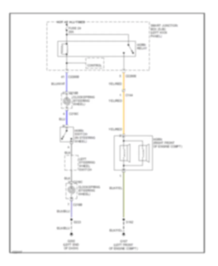
Horn Wiring Diagram, without Stripped Chassis for Ford E-350 Super Duty XLT 2014
List of elements for Horn Wiring Diagram, without Stripped Chassis for Ford E-350 Super Duty XLT 2014:
- C144
- C218b
- C218c
- C2280b
- C2280e
- Clockspring (steering wheel)
- Control
- Fuse 24 20a
- G107 (left front of engine compt)
- G202 (left end of dash)
- Horn (right front of engine compt)
- Horn relay
- Horn switch (in steering wheel)
- Hot at all times
- Left steering wheel switch
- S162
- S223
- Smart junction box (sjb) (left kick panel)