HORN
Horn Wiring Diagram, with Stripped Chassis for Ford E450 Super Duty 2010

List of elements for Horn Wiring Diagram, with Stripped Chassis for Ford E450 Super Duty 2010:
- 20a
- Battery junction box (bjb) (left front of engine compt)
- C218b
- C218c
- Clockspring (steering wheel)
- Fuse 34
- G101 (left front corner of engine compt)
- G207 (center of dash)
- Horn (right front of engine compt)
- Horn relay
- Horn switch
- Hot at all times
- Left steering wheel switch
- S123 (engine control sensor wiring harness, near breakout to horn)
- S260 (main wiring harness, near breakout to g207)
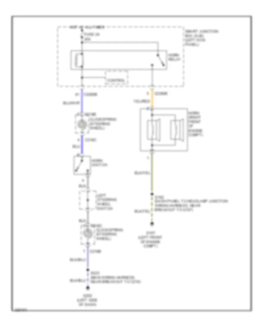
Horn Wiring Diagram, without Stripped Chassis for Ford E450 Super Duty 2010
List of elements for Horn Wiring Diagram, without Stripped Chassis for Ford E450 Super Duty 2010:
- 20a
- C218b
- C218c
- C2280b
- C2280e
- Clockspring (steering wheel)
- Control
- Engine compt)
- Fuse 24
- G107 (left front of engine compt)
- G202 (left side of dash)
- Horn (right front of
- Horn relay
- Horn switch
- Hot at all times
- Left steering wheel switch
- S223 (main wiring harness, near breakout to c210)
- Smart junction box (sjb) (left kick panel)