HORN
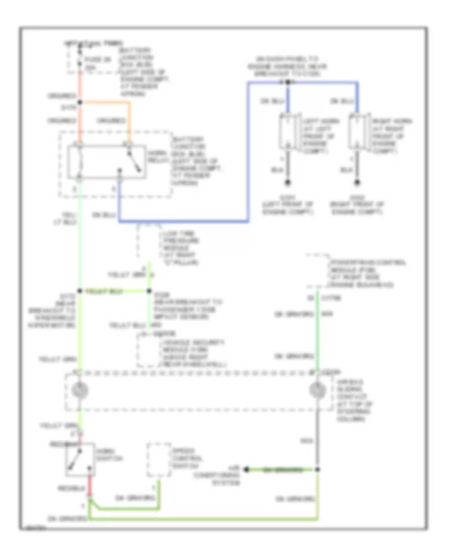
Horn Wiring Diagram for Ford Explorer 2005
List of elements for Horn Wiring Diagram for Ford Explorer 2005:
- (in dash panel to engine harness, near breakout to c126) s124
- 20a
- Air bag sliding contact (at top of steering column)
- Air conditioning system
- Battery junction box (bjb) (left side of engine compt, at fender apron)
- C175b
- C218a
- C3203e
- Fuse 28
- G101 (left front of engine compt)
- G103 (right front of engine compt)
- Horn relay
- Horn switch
- Hot at all times
- Left horn (at left front of engine compt)
- Low tire pressure module (at right "c" pillar)
- Nca
- Powertrain control module (pcm) (at right side engine bulkhead)
- Right horn (at right front of engine compt)
- S170
- S172 (near breakout to windshield wiper motor)
- S328 (near breakout to passenger 1 side impact sensor)
- Speed control switch
- Vehicle security module (vsm) (above right rear wheelwell)
 English