
HORN
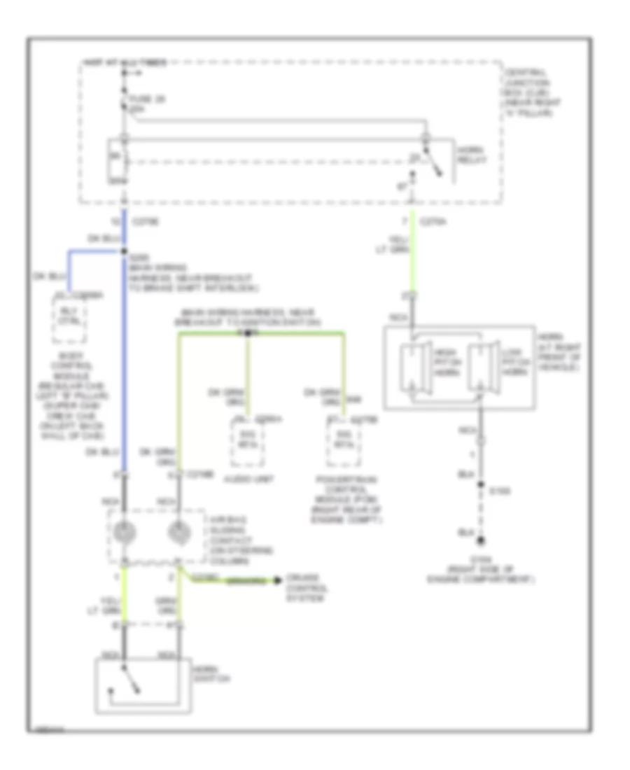
Horn Wiring Diagram for Ford Pickup F350 Super Duty 2004
List of elements for Horn Wiring Diagram for Ford Pickup F350 Super Duty 2004:
AIR CONDITIONINGBODY CONTROL MODULESENGINE PERFORMANCEANTI-LOCK BRAKESANTI-THEFTCRUISE CONTROLCOMPUTER DATA LINESDEFOGGERSEXTERIOR LIGHTSHEADLIGHTSGROUND DISTRIBUTIONNAVIGATIONINSTRUMENT CLUSTERMEMORY SYSTEMSINTERIOR LIGHTSHORNPOWER DOOR LOCKSPOWER DISTRIBUTIONPOWER MIRRORSRADIOPOWER WINDOWSPOWER TOP/SUNROOFPOWER SEATSSTARTING/CHARGINGTRANSMISSIONSUPPLEMENTAL RESTRAINTSSHIFT INTERLOCKWARNING SYSTEMSWIPER/WASHER