
HORN
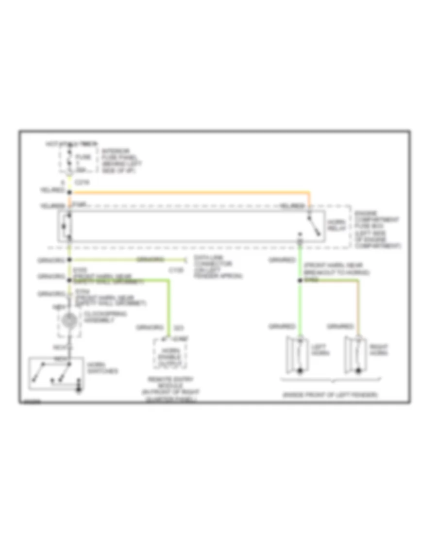
Horn Wiring Diagram for Ford Probe GT 1997
List of elements for Horn Wiring Diagram for Ford Probe GT 1997:
AIR CONDITIONINGANTI-LOCK BRAKESCOOLING FANBODY COMPUTERCOMPUTER DATA LINESCRUISE CONTROLDEFOGGERSGROUND DISTRIBUTIONENGINE PERFORMANCEHEADLIGHTSINTERIOR LIGHTSEXTERIOR LIGHTSHORNINSTRUMENT CLUSTERPOWER SEATSPOWER DOOR LOCKSRADIOPOWER MIRRORSPOWER TOP/SUNROOFSHIFT INTERLOCKSPOWER DISTRIBUTIONPOWER WINDOWSSTARTING/CHARGINGWARNING SYSTEMSTRANSMISSIONSUPPLEMENTAL RESTRAINTSWIPER/WASHER