
HORN
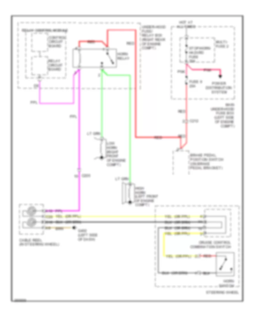
Horn Wiring Diagram for Honda Odyssey Touring 2013
List of elements for Horn Wiring Diagram for Honda Odyssey Touring 2013:
TRANSMISSIONTRUNK, TAILGATE, FUEL DOORWARNING SYSTEMSWIPER/WASHERANTI-LOCK BRAKESBODY CONTROL MODULESANTI-THEFTAIR CONDITIONINGCOOLING FANCOMPUTER DATA LINESDEFOGGERSENGINE PERFORMANCEEXTERIOR LIGHTSCRUISE CONTROLHEADLIGHTSHORNGROUND DISTRIBUTIONINTERIOR LIGHTSPOWER DISTRIBUTIONMEMORY SYSTEMSNAVIGATIONPOWER DOOR LOCKSINSTRUMENT CLUSTERPOWER MIRRORSPOWER SEATSSTARTING/CHARGINGRADIOPOWER TOP/SUNROOFSUPPLEMENTAL RESTRAINTSSHIFT INTERLOCKPOWER WINDOWS