HORN
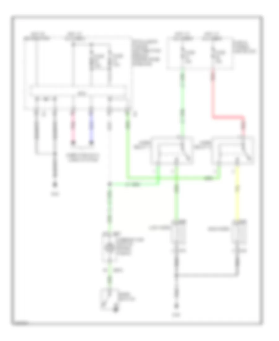
Horn Wiring Diagram, Coupe for Infiniti G35 2007

List of elements for Horn Wiring Diagram, Coupe for Infiniti G35 2007:
- Can-h
- Can-l
- Combination switch (spiral cable)
- Computer data lines system
- Cpu
- E17 (on right side of engine compartment)
- E32
- E33
- E35
- E36
- E43 (on left front side of engine compt)
- Fuse & fusible link & relay box (right rear of engine compt)
- Fuse 10a
- Fuse 15a
- Gnd (power)
- Gnd (signal)
- High horn (right front of engine compt, behind grille)
- Horn relay (in fuse, fusible link & relay box)
- Horn rly
- Horn switch
- Hot at all times
- Intelligent power distribution module engine room (ipdm e/r) (right rear of engine compt)
- Low horn (right front of engine compt, behind grille)
- M203
- M23
- Nca
Horn Wiring Diagram, Sedan for Infiniti G35 2007
List of elements for Horn Wiring Diagram, Sedan for Infiniti G35 2007:
- Combination switch (spiral cable)
- Computer data lines system
- Cpu
- E22
- E46
- E61
- E62
- E69
- E70
- Fuse & fusible link block
- Fuse 10a
- Fuse 15a
- High horn
- Horn relay 1
- Horn relay 2
- Horn switch
- Hot at all times
- Hot in on or start
- Intelligent power distribution module engine room (ipdm e/r)
- Low horn
- M303
- M36
- Pnk
- Red
 English