
HORN
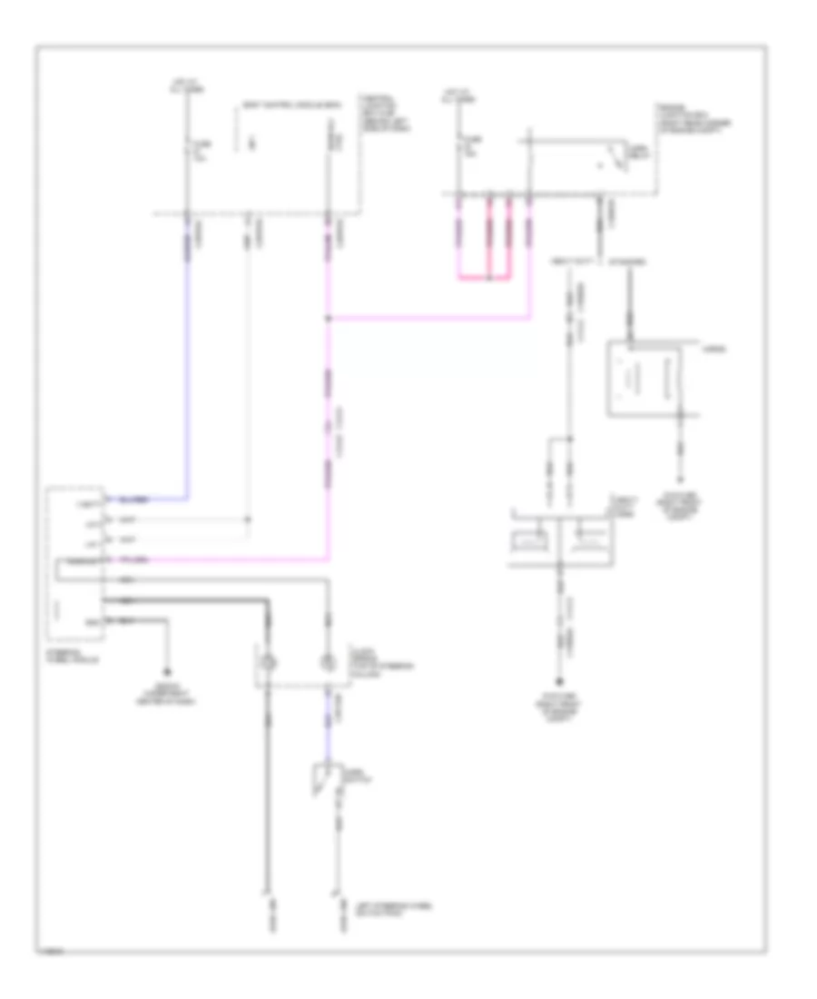
Horn Wiring Diagram for Land Rover Range Rover 2013
List of elements for Horn Wiring Diagram for Land Rover Range Rover 2013:
RADIOSHIFT INTERLOCKSTARTING/CHARGINGSUPPLEMENTAL RESTRAINTSTRANSMISSIONTRUNK, TAILGATE, FUEL DOORWARNING SYSTEMSWIPER/WASHERACTIVE BODYWORKSAIR CONDITIONINGANTI-LOCK BRAKESANTI-THEFTBODY CONTROL MODULESCOMPUTER DATA LINESCOOLING FANCRUISE CONTROLDEFOGGERSELECTRONIC POWER STEERINGELECTRONIC SUSPENSIONENGINE PERFORMANCEEXTERIOR LIGHTSGROUND DISTRIBUTIONHEADLIGHTSHORNINSTRUMENT CLUSTERINTERIOR LIGHTSMEMORY SYSTEMSNAVIGATIONPOWER DISTRIBUTIONPOWER DOOR LOCKSPOWER MIRRORSPOWER TOP/SUNROOFPOWER SEATSPOWER WINDOWS