
HORN
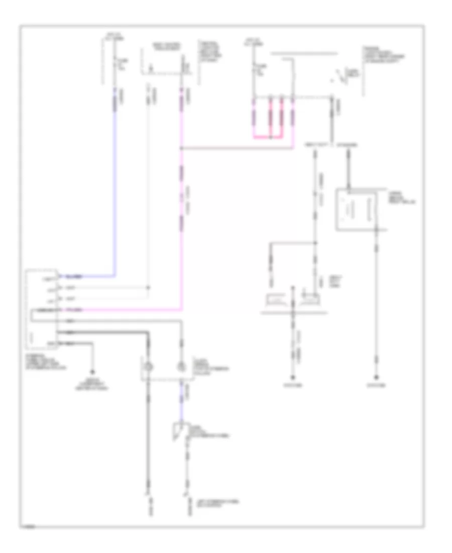
Horn Wiring Diagram for Land Rover Range Rover 2014
List of elements for Horn Wiring Diagram for Land Rover Range Rover 2014:
SHIFT INTERLOCKRADIOWARNING SYSTEMSSUPPLEMENTAL RESTRAINTSTRUNK, TAILGATE, FUEL DOORSTARTING/CHARGINGTRANSMISSIONANTI-THEFTANTI-LOCK BRAKESCOMPUTER DATA LINESWIPER/WASHERAIR CONDITIONINGCOOLING FANBODY CONTROL MODULESCRUISE CONTROLDEFOGGERSELECTRONIC POWER STEERINGELECTRONIC SUSPENSIONEXTERIOR LIGHTSHORNENGINE PERFORMANCEINSTRUMENT CLUSTERGROUND DISTRIBUTIONHEADLIGHTSINTERIOR LIGHTSNAVIGATIONPOWER DISTRIBUTIONPOWER DOOR LOCKSMEMORY SYSTEMSPOWER SEATSPOWER WINDOWSPOWER MIRRORSPOWER TOP/SUNROOF