HORN
Horn Wiring Diagram, with Power Equipment for Mazda B2500 SX 2001

List of elements for Horn Wiring Diagram, with Power Equipment for Mazda B2500 SX 2001:
- 15a
- 20a
- 7.5a
- Battery junction box (left rear of engine compt)
- Central junction box (behind left side of dash)
- Central security module (behind right upper side of dash)
- Clock spring
- Cruise control system
- Fuse 11
- Fuse 33
- Fuse 8
- G105 (rear of right front fender apron)
- G200 (left kick panel)
- G203 (right kick) panel)
- Horn (right front side of engine compartment)
- Horn switch
- Hot at all times
- Hot in run or start
- Nca
- Ohms
- Steering wheel
- T-409
- T-410
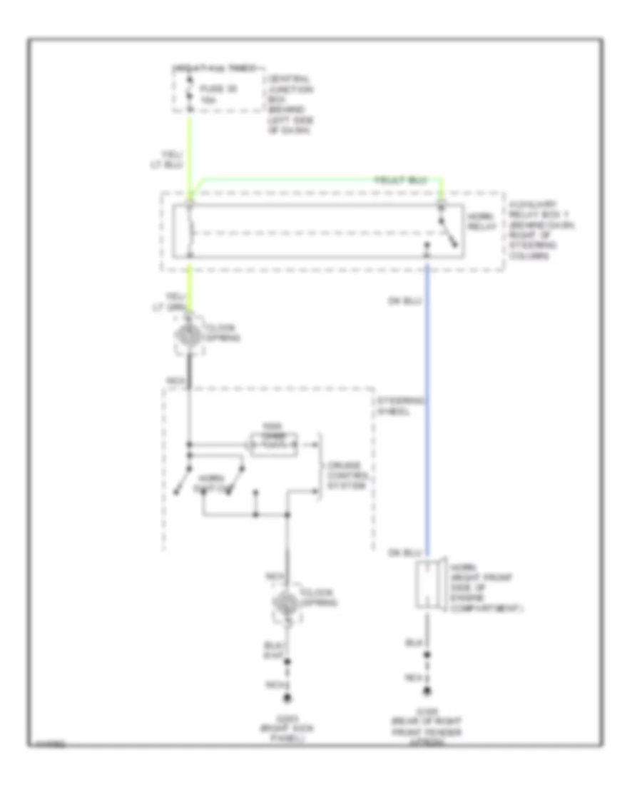
Horn Wiring Diagram, without Power Equipment for Mazda B2500 SX 2001
List of elements for Horn Wiring Diagram, without Power Equipment for Mazda B2500 SX 2001:
- 15a
- Auxiliary relay box 1 (behind dash, right of steering column)
- Central junction box (behind left side of dash)
- Clock spring
- Cruise control system
- Fuse 35
- G105 (rear of right front fender apron)
- G203 (right kick panel)
- Horn (right front side of engine compartment)
- Horn relay
- Horn switch
- Hot at all times
- Nca
- Ohms
- Steering wheel