
HORN
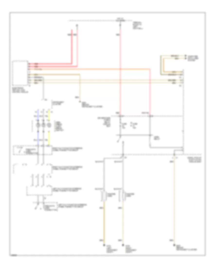
Horn Wiring Diagram for Mercedes-Benz CLK320 1999
List of elements for Horn Wiring Diagram for Mercedes-Benz CLK320 1999:
AIR CONDITIONINGANTI-THEFTCOOLING FANBODY COMPUTERANTI-LOCK BRAKESCOMPUTER DATA LINESEXTERIOR LIGHTSCRUISE CONTROLDEFOGGERSHEADLIGHTSGROUND DISTRIBUTIONHORNINTERIOR LIGHTSMEMORY SYSTEMSINSTRUMENT CLUSTERPOWER DOOR LOCKSPOWER MIRRORSPOWER SEATSPOWER TOP/SUNROOFNAVIGATIONRADIOPOWER DISTRIBUTIONPOWER WINDOWSSUPPLEMENTAL RESTRAINTSTRANSMISSIONSHIFT INTERLOCKSTRUNK, TAILGATE, FUEL DOORSTARTING/CHARGINGWIPER/WASHER