
HORN
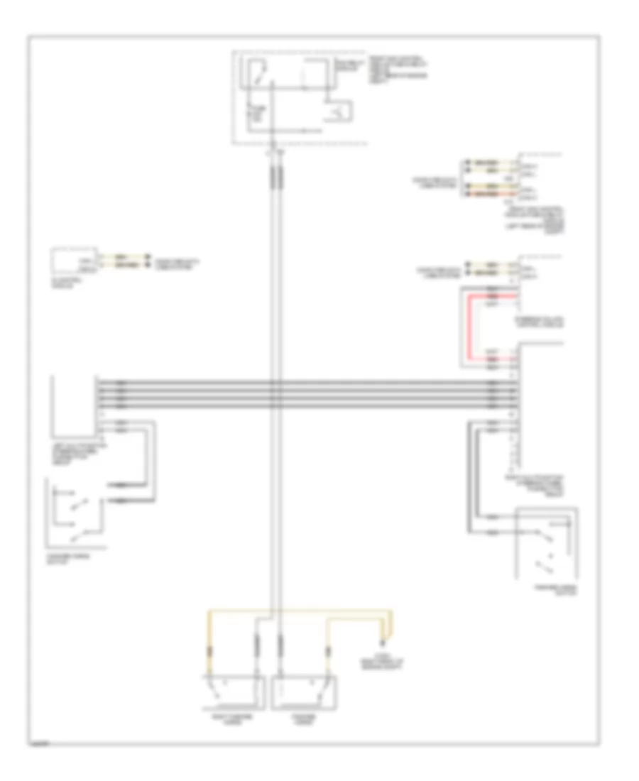
Horn Wiring Diagram for Mercedes-Benz CLK500 2005
List of elements for Horn Wiring Diagram for Mercedes-Benz CLK500 2005:
BODY CONTROL MODULESAIR CONDITIONINGANTI-LOCK BRAKESANTI-THEFTCOMPUTER DATA LINESCOOLING FANCRUISE CONTROLDEFOGGERSELECTRONIC POWER STEERINGENGINE PERFORMANCEGROUND DISTRIBUTIONHORNHEADLIGHTSEXTERIOR LIGHTSINSTRUMENT CLUSTERINTERIOR LIGHTSPASSIVE RESTRAINTSNAVIGATIONPOWER MIRRORSMEMORY SYSTEMSPOWER DISTRIBUTIONPOWER WINDOWSRADIOPOWER DOOR LOCKSSHIFT INTERLOCKPOWER SEATSTRANSMISSIONPOWER TOP/SUNROOFWARNING SYSTEMSSTARTING/CHARGINGSUPPLEMENTAL RESTRAINTSTRUNK, TAILGATE, FUEL DOORWIPER/WASHER