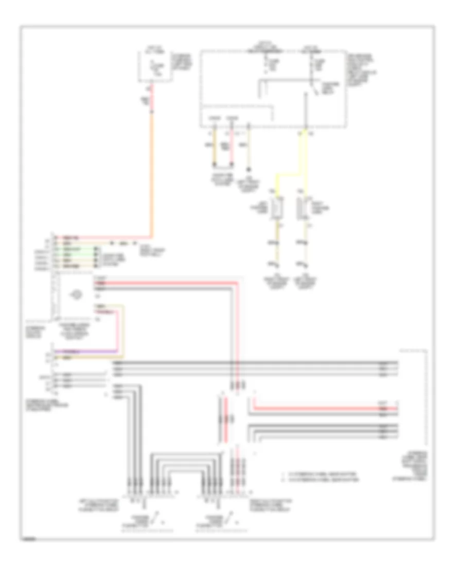
HORN
Horn Wiring Diagram for Mercedes-Benz CLS550 2008
List of elements for Horn Wiring Diagram for Mercedes-Benz CLS550 2008:
- (or nca)
- Can-b h
- Can-b l
- Can-c h
- Can-c l
- Computer data lines system
- Data
- Driver-side sam control module w/ fuse & relay module (left side of engine compt)
- Fanfare horn relay
- Fanfare horns and airbag clock spring contact
- Fanfare horns pushbutton
- Fuse 53a 15a
- Fuse 53b 15a
- Fuse 7.5a
- Hot at all times
- Hot w/ circuit 15r relay energized
- I13
- Interior fuse box (left end of dash)
- Left fanfare horn
- Left multifunction steering wheel pushbutton group
- Nca
- Red
- Right fanfare horn
- Right multifunction steering wheel pushbutton group
- Steering column module
- Steering wheel gear shift signal processing module (inside steering wheel)
- Steering wheel heater electronics (if equipped)
- W/ steering wheel gear shifter
- W/o steering wheel gear shifter
- W15/1 (right front footwell)
- W2 (right front of engine compt)
- W9 (left front of engine compt)
 English