HORN
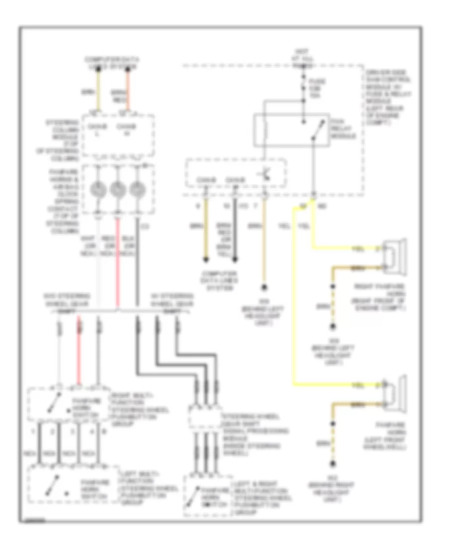
Horn Wiring Diagram for Mercedes-Benz E550 2007
List of elements for Horn Wiring Diagram for Mercedes-Benz E550 2007:
- Can-b h
- Can-b l
- Computer data lines system
- Driver side sam control module w/ fuse & relay module (left rear of engine compt)
- Fan relay module
- Fanfare horn (left front wheelwell)
- Fanfare horn switch
- Fanfare horns & air bag clock spring contact (top of steering column)
- Fuse 53b 15a
- Hot at all times
- I13
- Left & right multi-function steering wheel pushbutton group
- Left multi- function steering wheel pushbutton group
- Nca
- Red
- Red (or nca)
- Right fanfare horn (right front of engine compt)
- Right multi- function steering wheel pushbutton group
- Steering column module (top of steering column)
- Steering wheel gear shift signal processing module (inside steering wheel)
- W/ steering
- W/o steering
- W2 (behind right headlight unit)
- W9 (behind left headlight unit)
- Wheel gear shift
 English