HORN
Horn Wiring Diagram for Mercedes-Benz ML550 2012
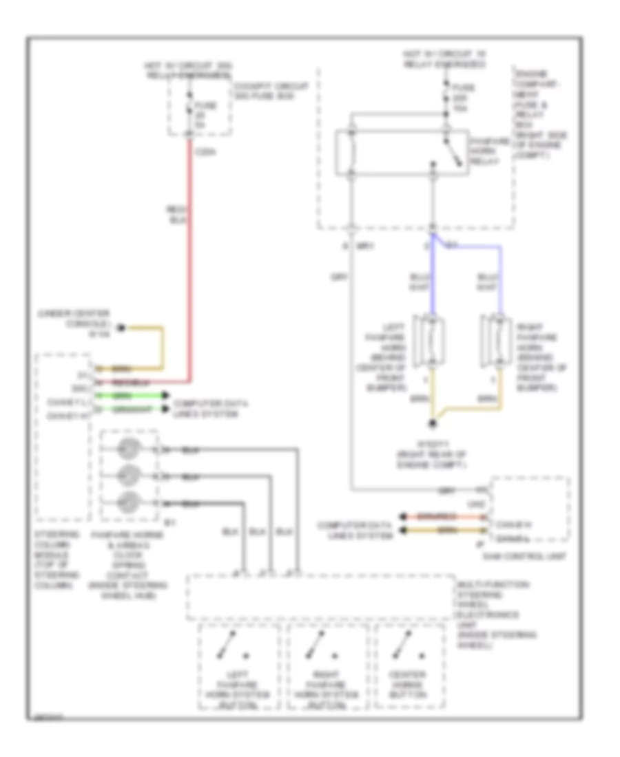
List of elements for Horn Wiring Diagram for Mercedes-Benz ML550 2012:
- (under center console) w1/4
- 30g
- Button
- C20a
- Can-b h
- Can-b l
- Can-e1 h
- Can-e1 l
- Center horns button
- Cockpit circuit 30g fuse box
- Computer data lines system
- Engine compart- ment fuse & relay box (right side of engine compt)
- Fanfare horn relay
- Fanfare horns & airbag clock spring contact (inside steering wheel hub)
- Fuse 15a
- Fuse 5a
- Hot w/ circuit 15 relay energized
- Hot w/ circuit 30g relay energized
- Left fanfare horn (behind center of front bumper)
- Left fanfare horn system
- Mr1
- Multi-function steering wheel electronics unit (inside steering wheel)
- Right fanfare horn (behind center of front bumper)
- Right fanfare horn system
- Sam control unit
- Steering column module (top of steering column)
- Uh2
- W52/11 (right rear of engine compt)
 English