HORN
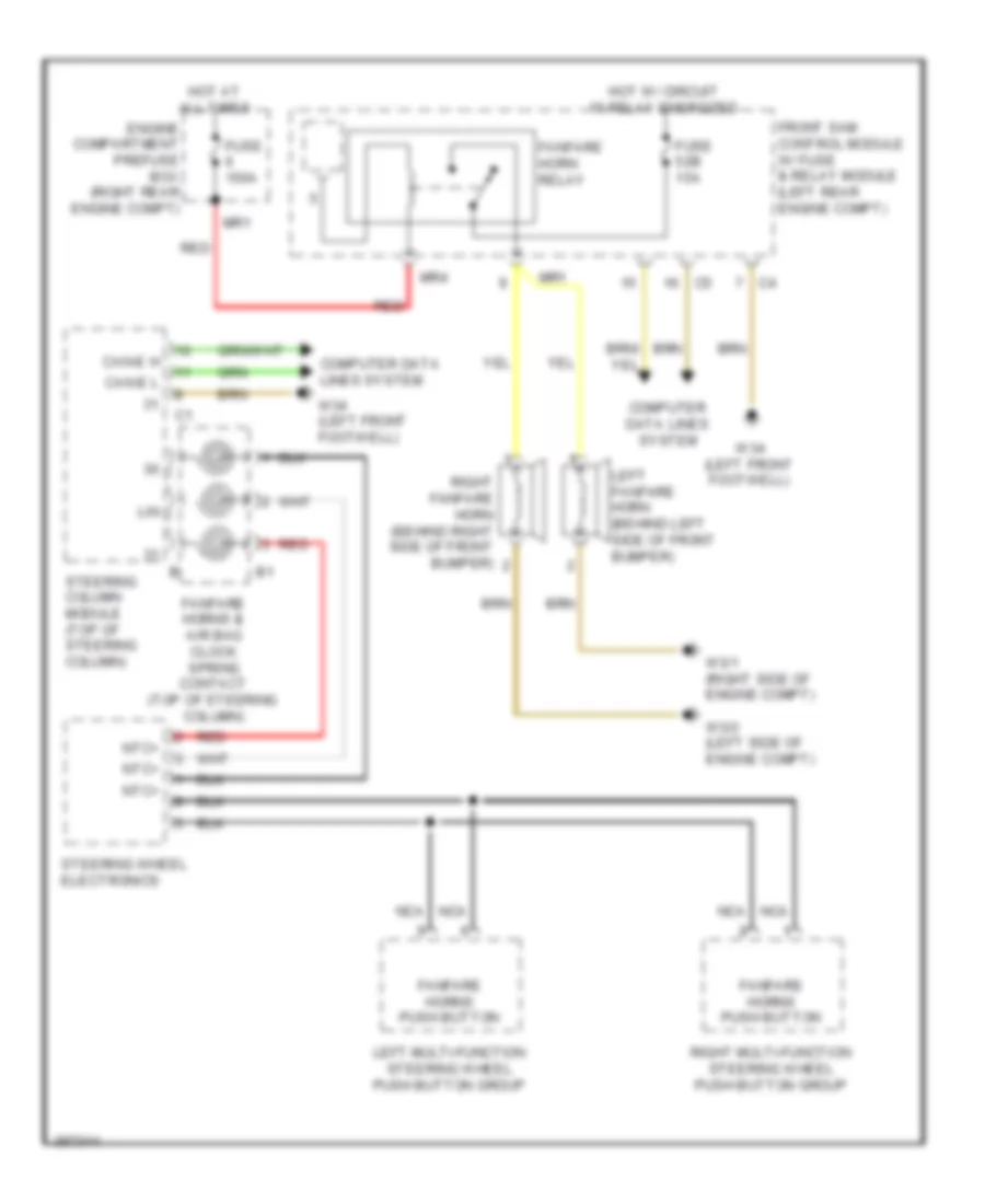
Horn Wiring Diagram for Mercedes-Benz S550 4Matic 2012
List of elements for Horn Wiring Diagram for Mercedes-Benz S550 4Matic 2012:
- Can-e h
- Can-e l
- Computer data lines system
- Engine compartment prefuse box (right rear engine compt)
- Fanfare horn relay
- Fanfare horns & air bag clock spring contact (top of steering column)
- Fanfare horns push button
- Front sam control module w/ fuse & relay module (left rear engine compt)
- Fuse 150a
- Fuse 52b 15a
- Hot at all times
- Hot w/ circuit 15 relay energized
- Left fanfare horn (behind left side of front bumper)
- Left multi-function steering wheel push button group
- Lin
- Mr1
- Mr4
- Nca
- Ntc+
- Red
- Right fanfare horn (behind right side of front bumper)
- Right multi-function steering wheel push button group
- Steering column module (top of steering column)
- Steering wheel electronics
- W3/1 (right side of engine compt)
- W3/2 (left side of engine compt)
- W34 (left front footwell)
 English