
HORN
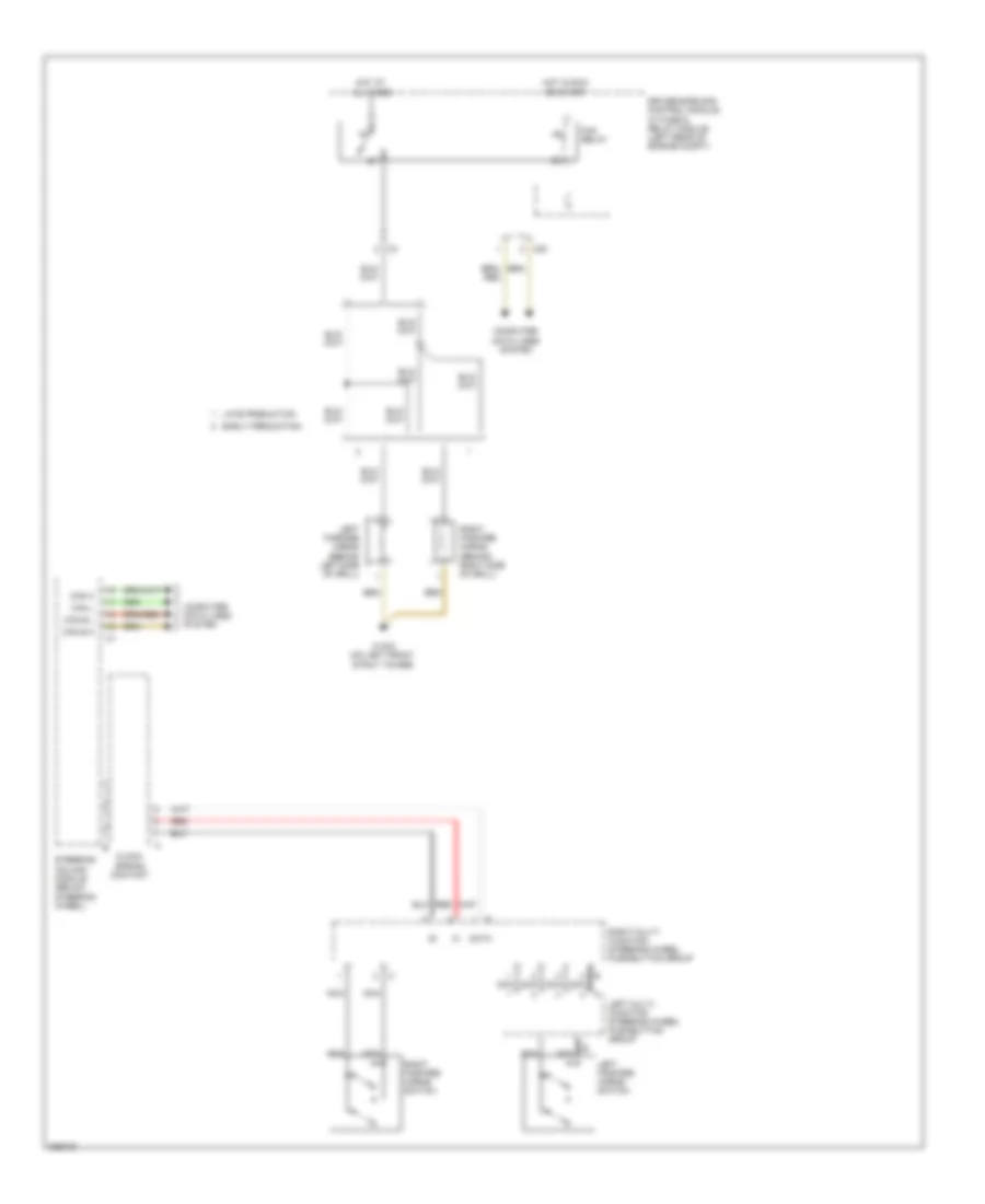
Horn Wiring Diagram for Mercedes-Benz SLK350 2006
List of elements for Horn Wiring Diagram for Mercedes-Benz SLK350 2006:
AIR CONDITIONINGANTI-LOCK BRAKESCOOLING FANANTI-THEFTBODY CONTROL MODULESCOMPUTER DATA LINESDEFOGGERSHORNEXTERIOR LIGHTSENGINE PERFORMANCEGROUND DISTRIBUTIONCRUISE CONTROLINTERIOR LIGHTSHEADLIGHTSINSTRUMENT CLUSTERNAVIGATIONPOWER DOOR LOCKSPOWER DISTRIBUTIONMEMORY SYSTEMSPOWER SEATSPOWER MIRRORSPOWER WINDOWSSTARTING/CHARGINGSHIFT INTERLOCKRADIOPOWER TOP/SUNROOFTRANSMISSIONSUPPLEMENTAL RESTRAINTSTRUNK, TAILGATE, FUEL DOORWARNING SYSTEMSWIPER/WASHER