
HORN
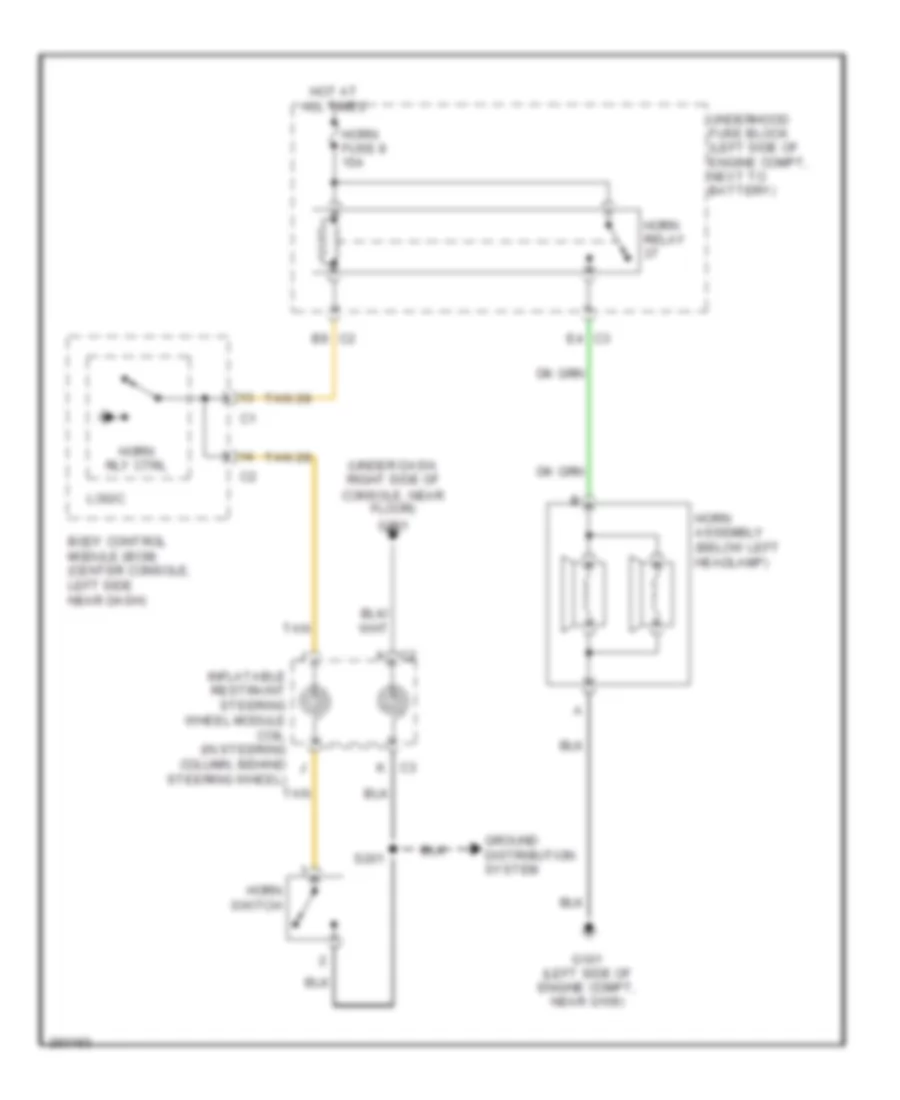
Horn Wiring Diagram for Saturn Aura Green Line 2007
List of elements for Horn Wiring Diagram for Saturn Aura Green Line 2007:
ANTI-THEFTAIR CONDITIONINGANTI-LOCK BRAKESBODY CONTROL MODULESDEFOGGERSELECTRONIC POWER STEERINGCRUISE CONTROLEXTERIOR LIGHTSCOOLING FANGROUND DISTRIBUTIONENGINE PERFORMANCEHEADLIGHTSCOMPUTER DATA LINESPOWER DISTRIBUTIONHORNINTERIOR LIGHTSPOWER TOP/SUNROOFINSTRUMENT CLUSTERPOWER DOOR LOCKSPOWER WINDOWSPOWER SEATSPOWER MIRRORSSHIFT INTERLOCKWARNING SYSTEMSRADIOSUPPLEMENTAL RESTRAINTSTRANSMISSIONTRUNK, TAILGATE, FUEL DOORSTARTING/CHARGINGWIPER/WASHER