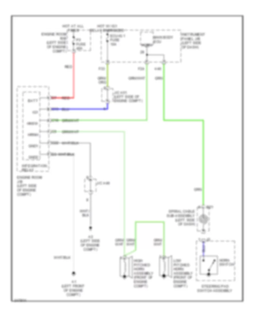
AUTOMOTIVE ELECTRICIANS PORTAL

HORN – Toyota Sienna LE 2011 – SYSTEM WIRING DIAGRAMS

HORN

Horn Wiring Diagram for Toyota Sienna LE 2011

Horn Wiring Diagram for Toyota Sienna LE 2011 https://portal-diagnostov.com/license.html
https://portal-diagnostov.com/license.html Automotive Electricians Portal FZCO Automotive Electricians Portal FZCO
Holen Sie sich Zugriff auf alle Schaltpläne AutoDownload PDF file

List of elements for Horn Wiring Diagram for Toyota Sienna LE 2011:

  • A1 (left front of engine compt)
  • A2 (left side of engine compt)
  • A40
  • Batt
  • C13
  • C18
  • C22
  • D21
  • Ecu-ig 1 fuse 10a
  • Engine room j/b (left side of engine compt)
  • Engine room r/b (left side of engine compt)
  • F24
  • F33
  • Gnd1
  • Gnd2
  • High pitched horn assembly (front of engine compt)
  • Hnsw
  • Horn
  • Horn switch
  • Hot at all times
  • Hot w/ ig1 relay energized
  • Hrnh
  • Ig1
  • Instrument panel j/b (left side of dash)
  • Integration relay
  • J/c a49
  • J/c a51 (left side of engine compt)
  • Low pitched horn assembly (front of engine compt)
  • Main body ecu
  • P/i fuse 40a
  • Red
  • Spiral cable sub-assembly (left side of dash)
  • Steering pad switch assembly