
HORN
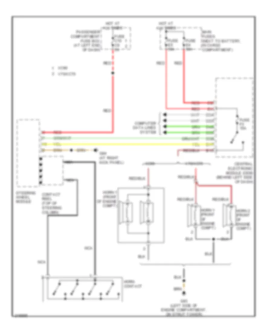
Horn Wiring Diagram for Volvo XC70 2006
List of elements for Horn Wiring Diagram for Volvo XC70 2006:
AIR CONDITIONINGANTI-LOCK BRAKESBODY CONTROL MODULESCOMPUTER DATA LINESCOOLING FANCRUISE CONTROLDEFOGGERSELECTRONIC POWER STEERINGELECTRONIC SUSPENSIONENGINE PERFORMANCEEXTERIOR LIGHTSGROUND DISTRIBUTIONHEADLIGHTSHORNINSTRUMENT CLUSTERINTERIOR LIGHTSMEMORY SYSTEMSNAVIGATIONPOWER DISTRIBUTIONPOWER DOOR LOCKSPOWER MIRRORSPOWER SEATSPOWER TOP/SUNROOFPOWER WINDOWSRADIOSHIFT INTERLOCKSTARTING/CHARGINGSUPPLEMENTAL RESTRAINTSTRANSMISSIONWARNING SYSTEMSWIPER/WASHERANTI-THEFT