Čeština
 Dansk
Dansk Deutsch
 Ελληνικά
 English
 English
 Español
 Suomi
Suomi Français
 Français
 עברית
עברית Magyar
 Italiano
 日本語
日本語 한국어
한국어 Nederlands
 Polski
 Português
 Português
 Română
 Русский
 Slovenčina
 Slovenščina
 Svenska
 Türkçe
 中文 (中国)

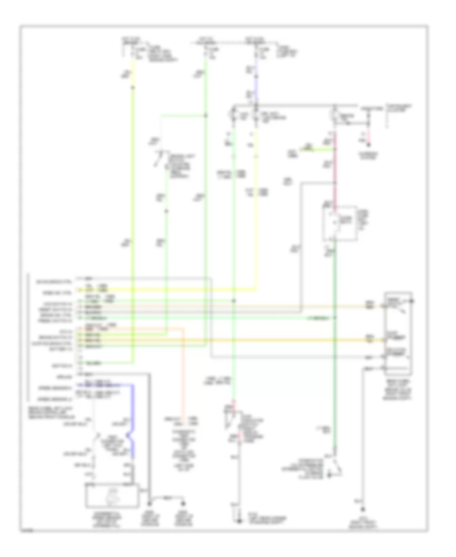
ANTI-LOCK BRAKES
All-Wheel ABS Wiring Diagram (1 of 2) for Isuzu Trooper SE 1996


List of elements for All-Wheel ABS Wiring Diagram (1 of 2) for Isuzu Trooper SE 1996:
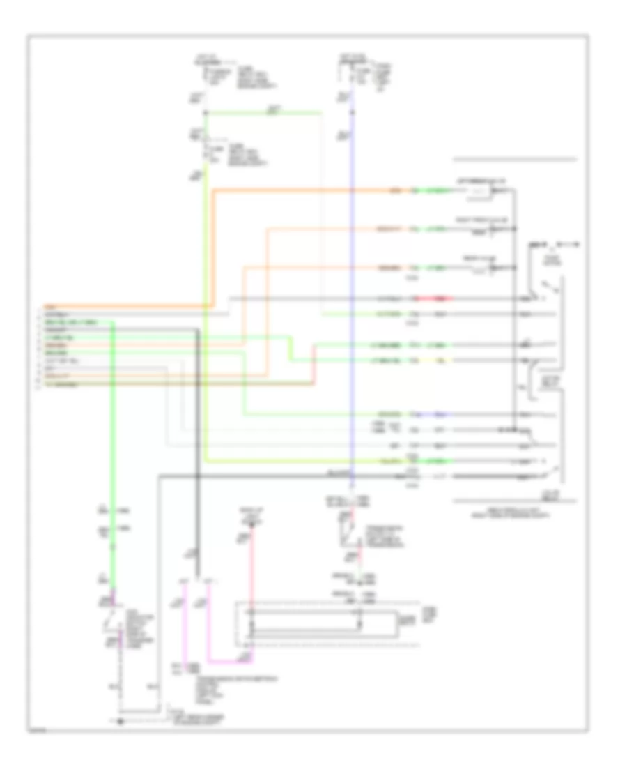
All-Wheel ABS Wiring Diagram (2 of 2) for Isuzu Trooper SE 1996
List of elements for All-Wheel ABS Wiring Diagram (2 of 2) for Isuzu Trooper SE 1996:
Rear Wheel ABS Wiring Diagram for Isuzu Trooper SE 1996
List of elements for Rear Wheel ABS Wiring Diagram for Isuzu Trooper SE 1996: