SUPPLEMENTAL RESTRAINTS
Supplemental Restraints Wiring Diagram for Isuzu Ascender S 2004
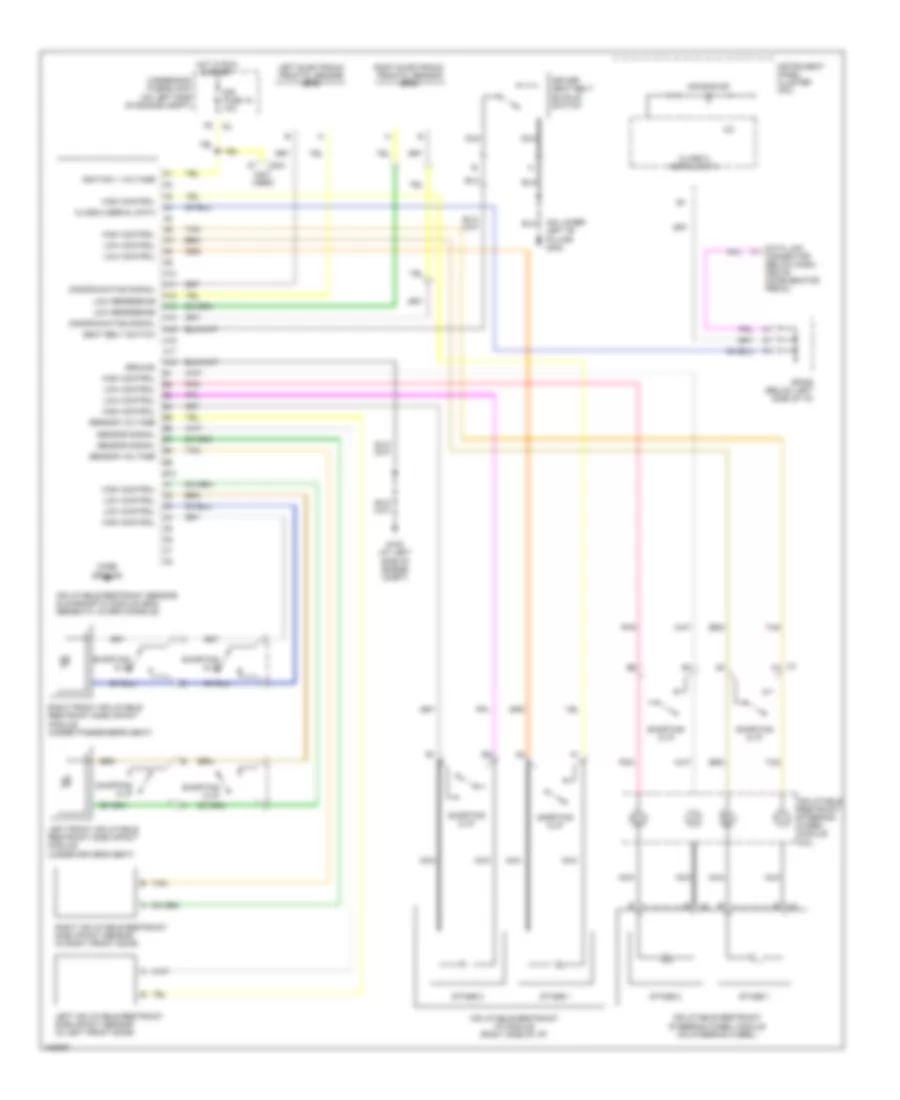
List of elements for Supplemental Restraints Wiring Diagram for Isuzu Ascender S 2004:
- (not used)
- (on lower left "b" pillar) g302
- 12v
- A10
- A11
- A12
- A13
- A14
- A15
- A16
- A17
- A18
- Air bag ind
- B10
- C1 a1
- C304
- Case ground
- Class 2 serial data
- Data link connector (below dash, above accelerator pedal)
- Discriminating signal
- Driver seat belt buckle switch
- G102 (at left side of engine compt)
- Ground
- High control
- Hot in run & start
- Ignition 1 voltage
- Inflatable restraint i/p module (right side of i/p)
- Inflatable restraint sensing & diagnostic module (sdm) (beneath lower console)
- Inflatable restraint steering wheel module (on steering wheel)
- Inflatable restraint steering wheel module coil
- Instrument panel cluster (ipc)
- Left electronic frontal sensor (efs)
- Left front inflatable restraint side impact module (under driver's seat)
- Left inflatable restraint side impact sensor (in left front door)
- Low control
- Low reference
- Nca
- Pnk
- Right electronic frontal sensor (efs)
- Right front inflatable restraint side impact module (under passenger's seat)
- Right inflatable restraint side impact sensor (in right front door)
- Seat belt switch
- Sensor signal
- Sensor voltage
- Shorting clip
- Sir fuse 18 10a
- Sp205 (below left side of i/p)
- Stage 1
- Stage 2
- Tan
- Underhood fuse block (on left side of engine compt)
 Čeština
 Dansk
Dansk Deutsch
 Ελληνικά
 English
 English
 Español
 Suomi
Suomi Français
 Français
 עברית
עברית Magyar
 Italiano
 日本語
日本語 한국어
한국어 Nederlands
 Polski
 Português
 Português
 Română
 Русский
 Slovenčina
 Slovenščina
 Svenska
 Türkçe
 中文 (中国)
 Hrvatski