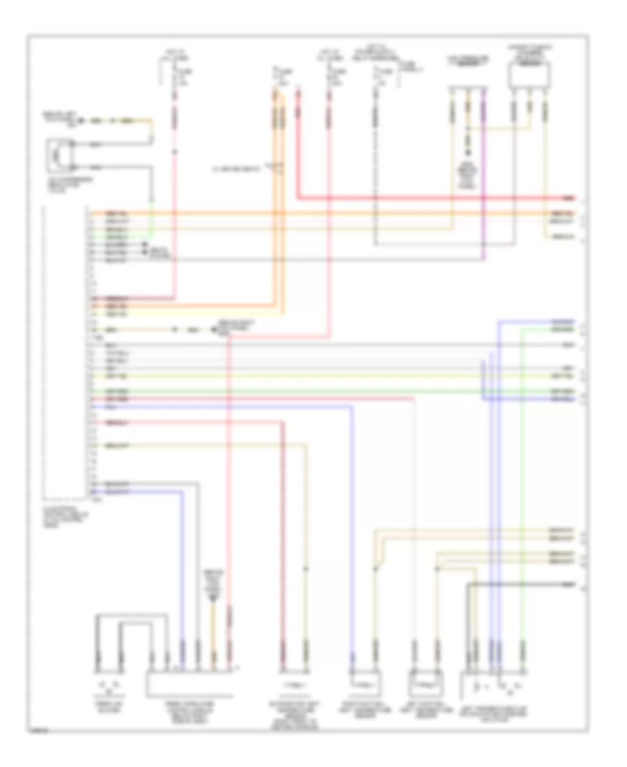
AIR CONDITIONING
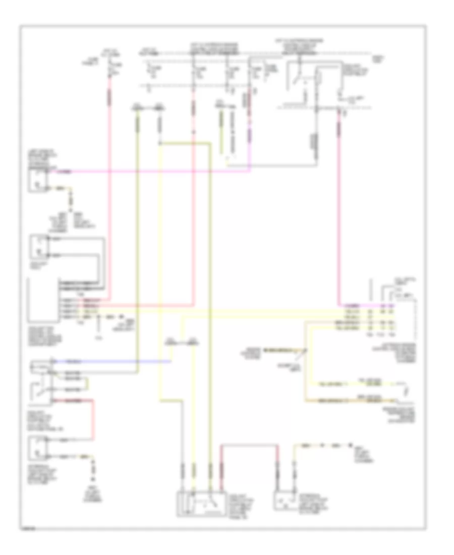
Automatic A/C Wiring Diagram, Early Production (1 of 3) for Audi A3 2008


List of elements for Automatic A/C Wiring Diagram, Early Production (1 of 3) for Audi A3 2008:
- (behind right kick panel) g638
- (in right plenum chamber) air quality sensor
- 16a
- 22a
- 37a
- A/c compressor regulator valve
- Climatronic control module (w a/c control head)
- Evaporator vent temperature sensor (right front of center console)
- Fresh air blower
- Fresh air blower control module (below right side of dash)
- Fresh air intake duct temperature sensor
- Fuse 10a
- Fuse 20a
- Fuse 40a
- Fuse 5a
- Fuse panel c
- G638 (behind right kick panel)
- High pressure sensor
- Hot at all times
- Left footwell vent temperature sensor
- Left temperature flap motor & potentiometer/ actuator
- Nca
- Red
- Right footwell vent temperature sensor
- Seats system
- T16d
- T20j
- W/ heated seats
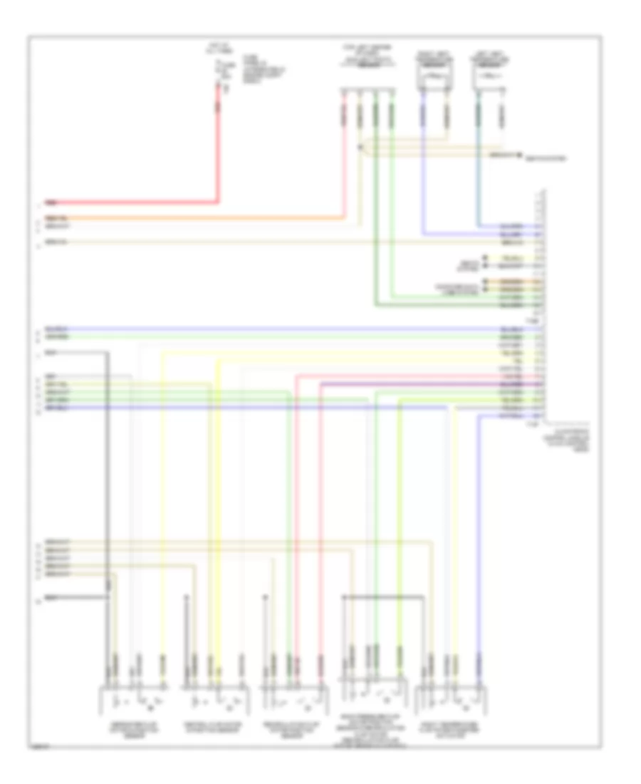
Automatic A/C Wiring Diagram, Early Production (2 of 3) for Audi A3 2008
List of elements for Automatic A/C Wiring Diagram, Early Production (2 of 3) for Audi A3 2008:
- (top left center of dash) sunlight photo sensor
- Back pressure flap motor position sensor & recirculation flap motor (recirculation flap motor: behind glove box)
- Central flap motor & position sensor
- Climatronic control module (w a/c control head)
- Computer data lines system
- Defroster flap motor & position sensor
- Fuse 50a
- Fuse panel b (integrated in engine compt e-box)
- Hot at all times
- Left vent temperature sensor
- Recirculation flap motor position sensor
- Red
- Right temperature flap potentiometer/ actuator
- Right vent temperature sensor
- Seats system
- T12f
- T16e
- T40
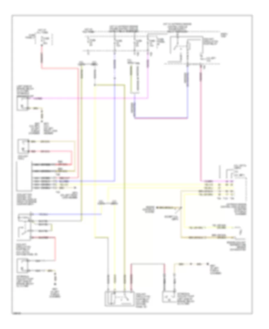
Automatic A/C Wiring Diagram, Early Production (3 of 3) for Audi A3 2008
List of elements for Automatic A/C Wiring Diagram, Early Production (3 of 3) for Audi A3 2008:
- (left side of engine, below oil filter) after-run coolant pump
- (or nca)
- (or red)
- 2.0l (bpy)
- 2.0l (cbfa)
- 2.0l (ccta)
- 2.0l (ccta), (cbfa)
- 2.0l bpy 3.2l
- 3.2l
- After-run coolant pump (left side of engine, below oil filter)
- Coolant circulation pump relay
- Coolant circulation pump relay (2.0l (cbfa)) (on fuse panel "b")
- Coolant circulation pump relay (2.0l (ccta)) (on fuse panel "b")
- Coolant fan 2
- Coolant fan control (fc) control module (front of engine compartment)
- E-box high
- Engine controls system
- Engine coolant temperature sensor (on radiator)
- Except 2.0l (cbfa)
- Fuse 10a
- Fuse 50a
- Fuse 5a
- Fuse panel a
- Fuse panel b
- G607 (2.0l bpy) (in left plenum chamber)
- G607 (in left plenum chamber)
- G673 (3.2l) (on left front long member)
- G673 (on left front long member)
- Hot at all times
- Motronic engine control module (ecm) (in center of plenum chamber)
- Nca
- Red
- Red (or nca)
- T121
- T26
- T2e
- T40
- T4d
- T94
Automatic A/C Wiring Diagram, Late Production (1 of 3) for Audi A3 2008
List of elements for Automatic A/C Wiring Diagram, Late Production (1 of 3) for Audi A3 2008:
- (behind left kick panel) g44
- (behind right kick panel) g638
- (in right plenum chamber) air quality sensor
- 16a
- 22a
- 37a
- A/c compressor regulator valve
- Climatronic control module (w a/c control head)
- Evaporator vent temperature sensor (right front of center console)
- Fresh air blower
- Fresh air blower control module (below right side of dash)
- Fuse 10a
- Fuse 20a
- Fuse 40a
- Fuse 5a
- Fuse panel c
- G638 (behind right kick panel)
- High pressure sensor
- Hot at all times
- Left footwell vent temperature sensor
- Left temperature flap motor & potentiometer/ actuator
- Nca
- Red
- Right footwell vent temperature sensor
- Seats system
- T16d
- T20j
- W/ heated seats
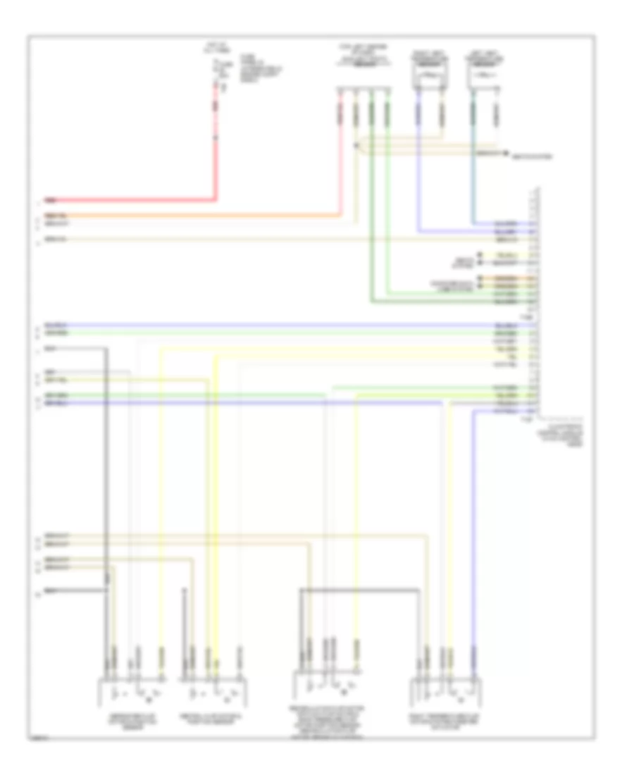
Automatic A/C Wiring Diagram, Late Production (2 of 3) for Audi A3 2008
List of elements for Automatic A/C Wiring Diagram, Late Production (2 of 3) for Audi A3 2008:
- (top left center of dash) sunlight photo sensor
- Central flap motor & position sensor
- Climatronic control module (w a/c control head)
- Computer data lines system
- Defroster flap motor & position sensor
- Fuse 50a
- Fuse panel b (integrated in engine compt e-box)
- Hot at all times
- Left vent temperature sensor
- Recirculation flap motor, air flow flap motor & back pressure flap motor position sensor (recirculation flap motor: behind glove box)
- Red
- Right temperature flap motor & potentiometer/ actuator
- Right vent temperature sensor
- Seats system
- T12f
- T16e
- T40
Automatic A/C Wiring Diagram, Late Production (3 of 3) for Audi A3 2008
List of elements for Automatic A/C Wiring Diagram, Late Production (3 of 3) for Audi A3 2008:
- (left side of engine, below oil filter) after-run coolant pump
- 2.0l (bpy)
- 2.0l (cbfa)
- 2.0l (ccta)
- 2.0l (ccta), (cbfa)
- 2.0l bpy 3.2l
- 3.2l
- After-run coolant pump (left side of engine, below oil filter)
- Coolant circulation pump relay
- Coolant circulation pump relay (2.0l (cbfa)) (on fuse panel "b")
- Coolant circulation pump relay (2.0l (ccta)) (on fuse panel "b")
- Coolant fan 2
- Coolant fan control (fc) control module (front of engine compartment)
- E-box high
- Engine controls system
- Engine coolant temperature sensor (on radiator)
- Except 2.0l (cbfa)
- Fuse 10a
- Fuse 50a
- Fuse 5a
- Fuse panel a
- Fuse panel b
- G607 (2.0l bpy) (in left plenum chamber)
- G607 (in left plenum chamber)
- G655 (3.2l) (on left headlight)
- G655 (on left headlight)
- Hot at all times
- Motronic engine control module (ecm) (in center of plenum chamber)
- Nca
- T121
- T26
- T2e
- T40
- T4d
- T94

 Čeština
 Dansk
Dansk Deutsch
 Ελληνικά
 English
 English
 Español
 Suomi
Suomi Français
 Français
 עברית
עברית Magyar
 Italiano
 日本語
日本語 한국어
한국어 Nederlands
 Polski
 Português
 Português
 Română
 Русский
 Slovenčina
 Slovenščina
 Svenska
 Türkçe
 中文 (中国)