POWER DISTRIBUTION
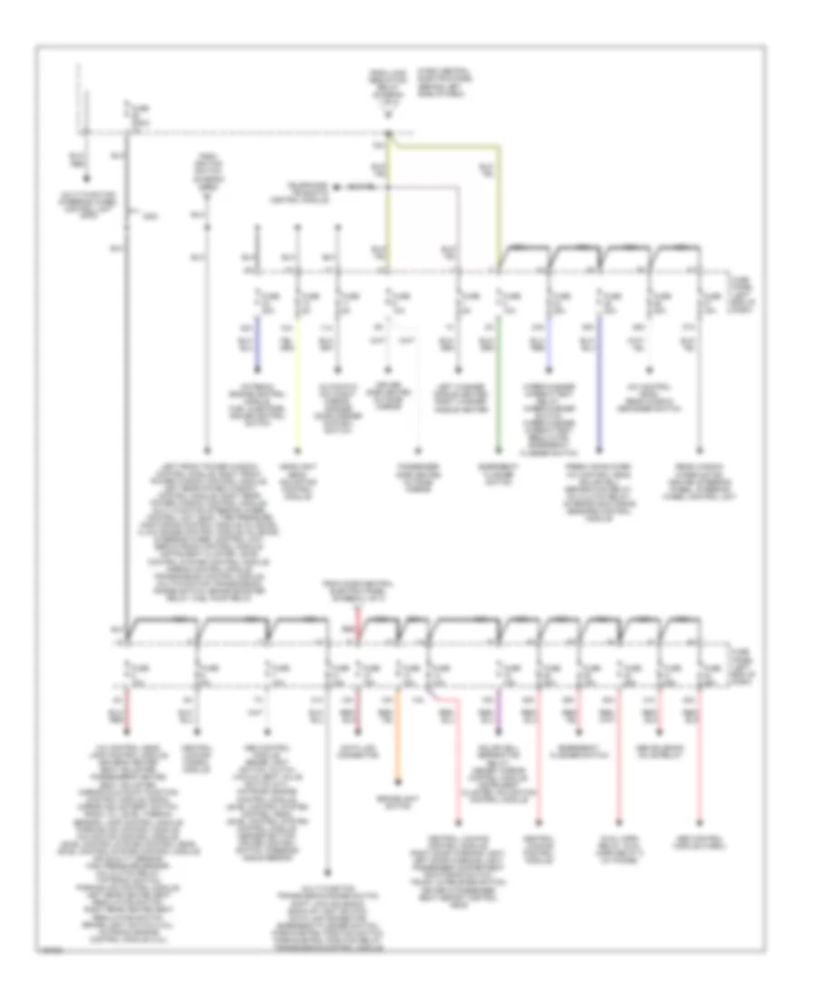
Power Distribution Wiring Diagram (1 of 3) for Audi A6 Avant Quattro 2003


List of elements for Power Distribution Wiring Diagram (1 of 3) for Audi A6 Avant Quattro 2003:
- (not used)
- 2.7l
- 3.0l
- 33a
- 50b
- 86s
- Battery
- Cigarette lighter
- Dual horn relay
- Fuel pump relay
- Fuse 15a
- Fuse 200a
- Fuse 5a
- Fuse panel (left end of dash)
- G81 (lower left "a" pillar)
- Headlight dimmer/ flasher switch
- Ignition switch
- Instrument cluster, central locking control module, steering column/ belt height adjustment control module
- Instrument cluster, generator, coolant fan control module, headlight beam adjusting control module
- Interior lights system
- Key-in ignition switch
- Light light switch switch
- Load reduction relay
- Micro central electric panel (behind left side of dash)
- Off
- Park/neutral position relay
- Rear cigarette lighter
- Red
- Run
- S1/
- Start
- Starter
- Starting interlock relay (13-fold relay panel)
- Telphone control module
- To fuse 12 (diagram 2 of 3)
- To fuse 5 (diagram 2 of 3)
- To micro central electric panel (diagram 2 of 3)
- To micro central electric panel (diagram 3 of 3)
- Voltage regulator/ generator (2.7l, 3.0l)
- Voltage regulator/ generator (4.2l only)
- Wiper/washer intermittent relay
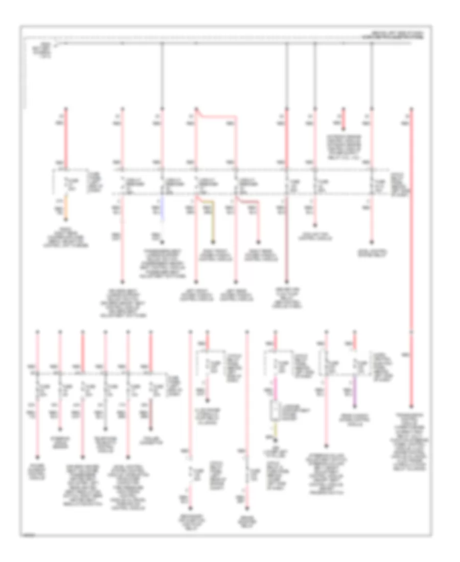
Power Distribution Wiring Diagram (2 of 3) for Audi A6 Avant Quattro 2003
List of elements for Power Distribution Wiring Diagram (2 of 3) for Audi A6 Avant Quattro 2003:
- 10a
- 11a
- 12a
- 13a
- 14a
- 15a
- 24a
- 25a
- 26a
- 27a
- 31a
- 32a
- 38a
- 39a
- 40a
- 41a
- 42a
- 75x
- A/c control head, lamp control module, driver's heated seat adjuster, passenger's heated seat adjuster, mirror fold-away function control module, radio, mirror adjustment switch, radio, oil level thermal sensor, lamp control module, parking aid control module, navigation control module, level control system control head, level control system control module, air quality sensor, high pressure sensor, a/c clutch relay, tiptronic switch, parking aid control module, left rear heated seat regulating switch, right rear heated seat regulating switch, brake light switch (4.2l), motronic engine control module (4.2l)
- A/c control head, rear window defogger switch
- Abs control module (w/edl)
- Abs control module, brake light switch, clutch vacuum vent valve switch (m/t), motronic engine control module, level control system control head, level control system control module, asr/esp button, cruise control switch, steering angle sensor
- Abs solenoid valve relay
- Automatic day/night mirror, garage door opener control switch
- Brakelight switch
- Central locking conrol module
- Central locking control module
- Central locking control module, right door warning light, left door warning light, passenger compartment monitoring switch, trunk lid release switch, driver & passenger seat memory control head
- Data link connector
- Driver side heated outside mirror
- Dual horn relay, dual horn relay 2 (w/ phone)
- Emergency flasher switch
- Fresh air blower, a/c control head, solar cell separation relay, a/c clutch relay, interior monitoring sensors control module
- From ignition switch (diagram 1 of 3)
- From load reduction relay (diagram 1 of 3)
- From micro central electric panel (diagram 1 of 3)
- Fuse (2003) 1a
- Fuse 10a
- Fuse 15a
- Fuse 20a
- Fuse 25a
- Fuse 30a
- Fuse 5a
- Fuse panel (left end of dash)
- Headlight beam adjusting control module
- Left front power window control module, right front power window control module, left rear power window control module, right rear power window control module, multi function steering wheel control unit (2002), tire pressure monitoring control module (allroad), 4-low range control module (allroad), steering wheel control unit, servotronic control module, instrument cluster, level control system control module, airbag control module, transmission control module, multi-function transmission range switch, brake booster relay, fuel pump relay
- Left washer nozzle heater, right washer nozzle heater
- Micro central electric panel (behind left side of dash)
- Motronic engine control module, fuel injectors, cruise control switch
- Multi function steering wheel control unit (2003)
- Multi function transmission range switch, shift lock solenoid, back-up light switch, data link connector, emergency flasher switch, park/nuetral position switch, park/nuetral position relay, transmission control module
- Nca
- Passenger side heated outside mirror
- Rear window wiper motor, heated steering wheel, steering wheel control unit
- Red
- Solar cell separation relay, memory mirror control module, instrument cluster, navigation control module
- Telephone/ telematic control module
- Wiper/washer intermittent relay, wiper/washer switch, wiper/washer intermittent regulator, emergency flasher switch
Power Distribution Wiring Diagram (3 of 3) for Audi A6 Avant Quattro 2003
List of elements for Power Distribution Wiring Diagram (3 of 3) for Audi A6 Avant Quattro 2003:
- (behind left side of dash) micro central electric panel
- 13-fold relay panel (behind left side of dash)
- 16a
- 17a
- 3-fold relay & fuse panel (behind lower left side of dash)
- 3-fold relay panel (left rear of engine compt)
- 30a
- 35a
- 37a
- 4-low range hydraulic pump relay (allroad)
- 44a
- 8-fold relay panel (behind left side of dash)
- Abs return flow pump relay, abs control module (w/edl)
- Brake booster relay
- Circuit breaker 30a
- Coolant fan control module
- Dirver's heated seat adjuster, passenger's heated seat adjuster, left rear heated seat regulating switch, right rear heated seat regulating switch
- Driver's seat lumbar support adjust switch, driver's memory seat control module, driver's seat adjustment switches
- From a battery (diagram 1 of 3)
- Fuse 10a
- Fuse 15a
- Fuse 20a
- Fuse 30a
- Fuse 40a
- Fuse 50a
- Fuse 5a
- Fuse 60a
- Fuse panel (left end of dash)
- Fuse s110 40a
- G86 (lower left "a" pillar)
- Left front power window control module
- Left rear power window control module
- Level control system control module, combustion air blower capacitor, tire pressure monitoring control module (allroad), parking aid control module
- Level control system relay
- Luggage compartment power socket
- Micro- central electric panel (behind left side of dash)
- Passenger's seat lumbar support adjust switch, passenger's memory seat control module, passenger seat adjustment switches
- Power sunroof control module
- Radio, right rear woofer/amplifier, aerial selection control unit (w/bose)
- Rear window shade control module
- Red
- Right front power window control module
- Right rear power window control module
- Secondary air injection (air) pump relay
- Steering angle sensor
- Steering column adjustment switch, steering column/ belt height adjustment control module, memory seat control module, memory program switch
- Telephone/ telematic control module
- Trailer connector
- Transmission control module, wiper/washer intermittent relay, multi function steering wheel control module, 4-low range control module (allroad), 4-low range hydraulic pump relay (allroad)

 Čeština
 Dansk
Dansk Deutsch
 Ελληνικά
 English
 English
 Español
 Suomi
Suomi Français
 Français
 עברית
עברית Magyar
 Italiano
 日本語
日本語 한국어
한국어 Nederlands
 Polski
 Português
 Português
 Română
 Русский
 Slovenčina
 Slovenščina
 Svenska
 Türkçe
 中文 (中国)