
 Čeština
 Dansk
Dansk Deutsch
 Ελληνικά
 English
 English
 Español
 Suomi
Suomi Français
 Français
 עברית
עברית Magyar
 Italiano
 日本語
日本語 한국어
한국어 Nederlands
 Polski
 Português
 Português
 Română
 Русский
 Slovenčina
 Slovenščina
 Svenska
 Türkçe
 中文 (中国)

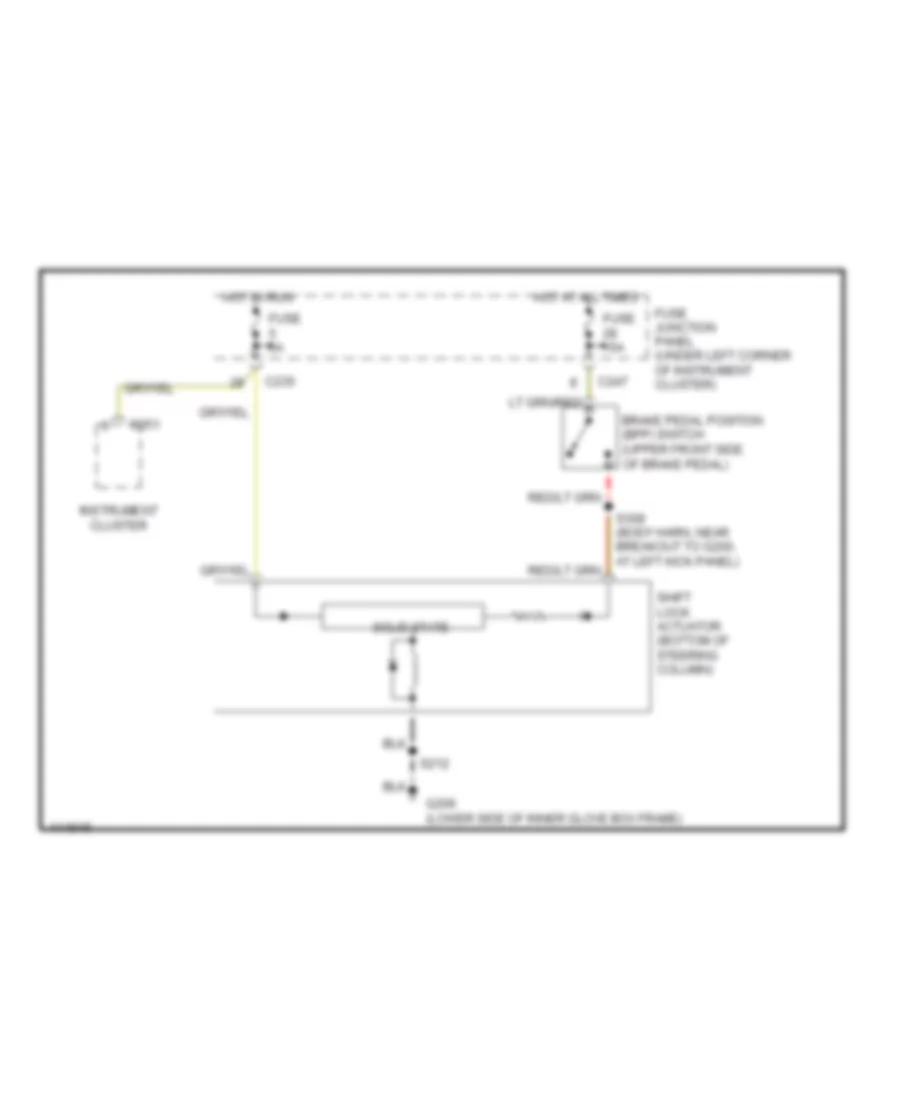
SHIFT INTERLOCKS
Shift Interlock Wiring Diagram for Mercury Sable LS 1999
List of elements for Shift Interlock Wiring Diagram for Mercury Sable LS 1999:

AIR CONDITIONINGANTI-LOCK BRAKESANTI-THEFTBODY COMPUTERCOMPUTER DATA LINESCOOLING FANCRUISE CONTROLDEFOGGERSELECTRONIC POWER STEERINGELECTRONIC SUSPENSIONENGINE PERFORMANCEEXTERIOR LIGHTSGROUND DISTRIBUTIONHEADLIGHTSHORNINSTRUMENT CLUSTERINTERIOR LIGHTSPOWER ANTENNAPOWER DISTRIBUTIONPOWER DOOR LOCKSPOWER MIRRORSPOWER SEATSPOWER TOP/SUNROOFPOWER WINDOWSRADIOSHIFT INTERLOCKSSTARTING/CHARGINGSUPPLEMENTAL RESTRAINTSTRANSMISSIONTRUNK, TAILGATE, FUEL DOORWARNING SYSTEMSWIPER/WASHER