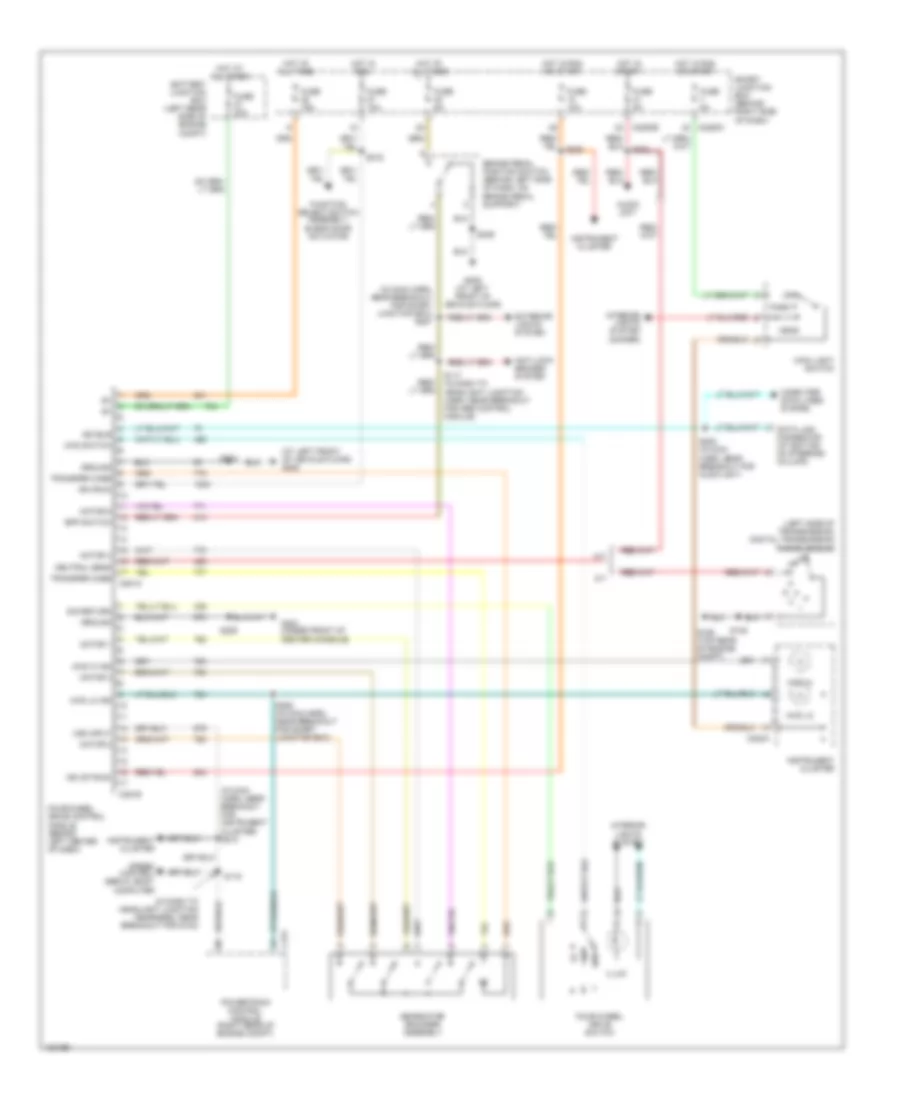
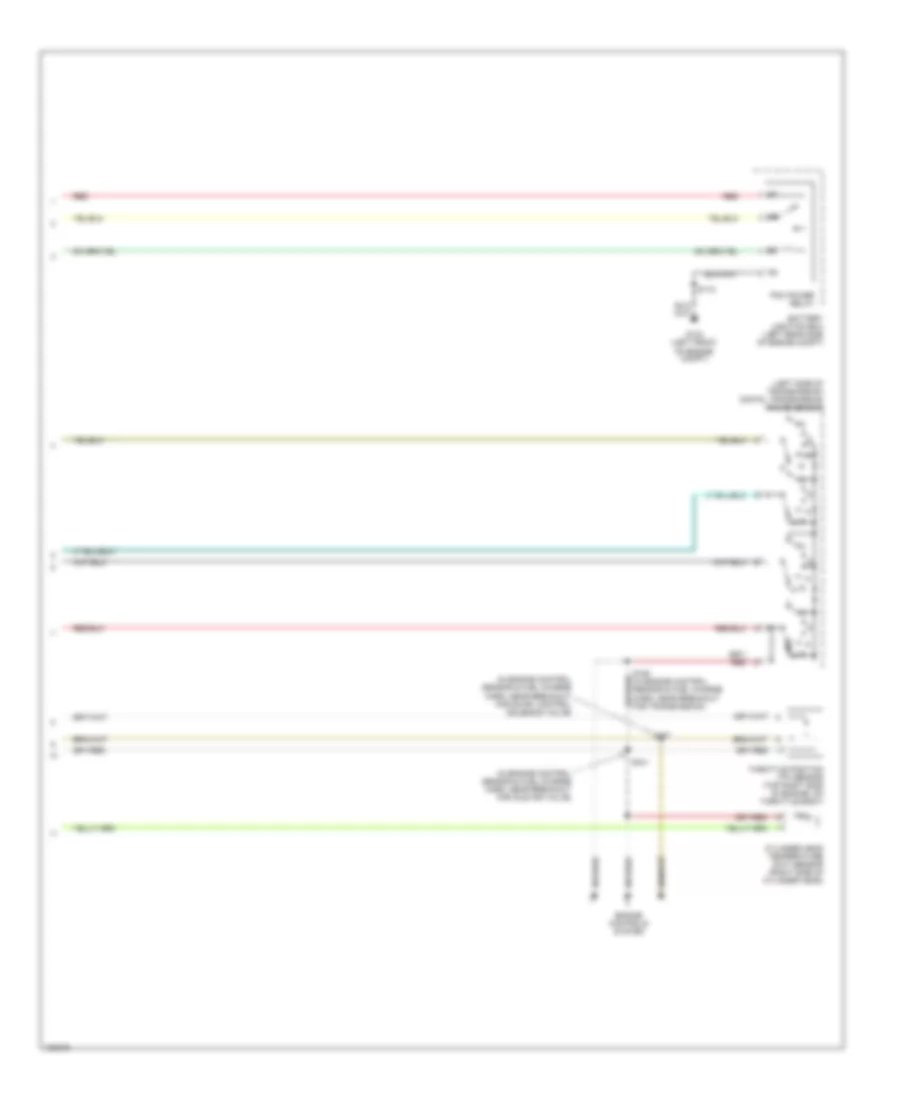
TRANSMISSION
4WD Wiring Diagram for Ford Ranger 2004
List of elements for 4WD Wiring Diagram for Ford Ranger 2004:
- (at left front of vehicle floor) g205
- (in dash to headlight junction hearness, near breakout for g102)
- (in main harn, near breakout for instrument cluster) s213
- (in main harn, near breakout for smart junction box) s227
- (left side of transmission) digital transmission range sensor
- 4wd hi
- 4wd hi ind
- 4wd lo
- 4wd lo ind
- 4wd switch
- A/t
- Anti-lock brakes system
- Audio unit
- Battery junction box (left rear side of engine compt)
- Bpp switch
- Brake pedal position switch (behind left side of dash, on brake pedal support)
- C175
- C220a
- C2280b
- C2280c
- C281a
- C281b
- Computer data lines system
- Data link connector (at bottom of steering column)
- Exterior lights system
- Four-wheel drive control module (behind left center of dash)
- Four-wheel drive switch
- Function select switch assembly, blend door actuator
- Fuse 10a
- Fuse 15a
- Fuse 20a
- Fuse 5a
- G106 (top rear of engine compt)
- G204 (under front of center console)
- G205 (at left front of vehicle floor)
- Gearmotor encoder assembly
- Ground
- Head
- Hot at all times
- Hot in run
- Hot in run or start
- Hot in start
- Ign (run)
- Ign (st/run)
- Illum
- Instrument cluster
- Interior lights system
- Interior lights system (dimmer)
- Iso bus
- M/t
- Main light switch
- Motor 1
- Motor 2
- Motor 3
- Motor 4
- Motor 5
- Neutral sens
- Off
- Park
- Powertrain control module (right rear of engine compt)
- S116
- S117 (in dash to headlight junction harn, near breakout for abs control module)
- S145
- S200
- S203
- S208 (in main harn. near breakout for audio unit)
- S209
- S216
- S223
- S236
- S258 (in main harn, near breakout for smart junction box)
- Sig return
- Smart junction box (behind right side of dash)
- Speed control servo, body computer
- Transfer case
- Vss input
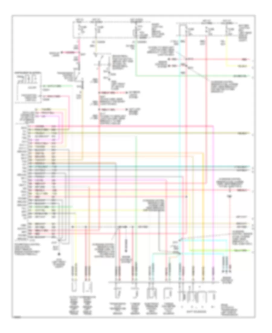
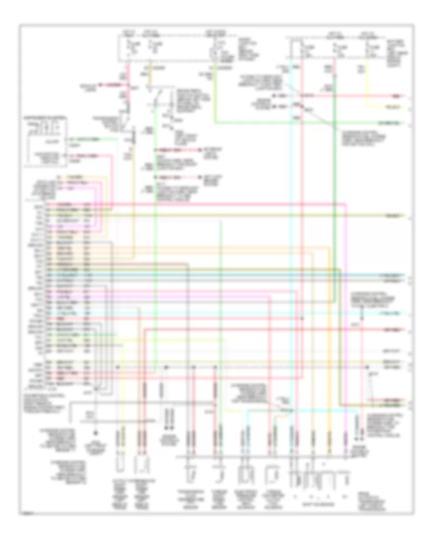
2.3L
2.3L, A/T Wiring Diagram (1 of 2) for Ford Ranger 2004
List of elements for 2.3L, A/T Wiring Diagram (1 of 2) for Ford Ranger 2004:
- (in dash to headlight junction harn, near breakout to battery junction box)
- (in engine control sensor & fuel charge harn, at breakout for powertrain control module)
- (in engine control sensor & fuel charge harn, near breakout for fuel injector 4)
- (in engine control sensor & fuel charge harn, near breakout for transmission)
- (in engine control sensor & fuel charge harn, near breakout to swirl control solenoid valve)
- 5r44e automatic transmission (left side of transmission)
- Anti-lock brakes system
- Back-up lamps
- Battery junction box (left rear side of engine compt)
- Bpp
- Brake pedal position switch (behind left side of dash, on brake pedal support)
- C175
- C220a
- C220b
- C2280b
- C2280ba
- Cht
- Connector (at bottom of steering column)
- Data link
- Dlc
- Dlc (+)
- Dlc (-)
- Electronic pressure control (epc) solenoid
- Engine controls system
- Epc
- Exterior lights system
- Fuse 10a
- Fuse 15a
- Fuse 30a
- Fuse 5a
- G104 (left front of engine compt)
- G205 (left front of vehicle floor)
- Ground
- Hot at all times
- Hot in run
- Hot in run or start
- Instrument cluster
- Intermediate shaft speed (iss) sensor (left side of trans)
- Iss
- Junction box)
- Malfunction indicator lamp (mil)
- Mil
- Nca
- O/d off
- Oss
- Output shaft speed (oss) sensor (left rear of trans)
- Pcm power diode
- Power
- Powertrain control module (pcm) (right rear of engine compartment, through firewall)
- Prndl
- Ptc 1a
- Red
- S107
- S113
- S117 (in dash to headlight junction harn, near breakout to abs control module)
- S143
- S149
- S150
- S153
- S154
- S236
- S237
- Shift solenoids
- Sig rtn
- Smart junction box (behind right side of dash)
- Ss a
- Ss b
- Ss c
- Ss d
- Tcc
- Tcil
- Tcs
- Tft
- Torque converter clutch (tcc) solenoid
- Tr1
- Tr2
- Tr3a
- Tr4
- Transmission control switch (tcs)
- Transmission fluid temperature (tft) sensor
- Tss
- Turbine shaft speed (tss) sensor
- Vbatt
- Vref
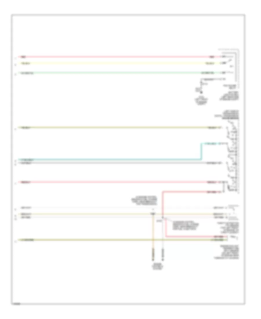
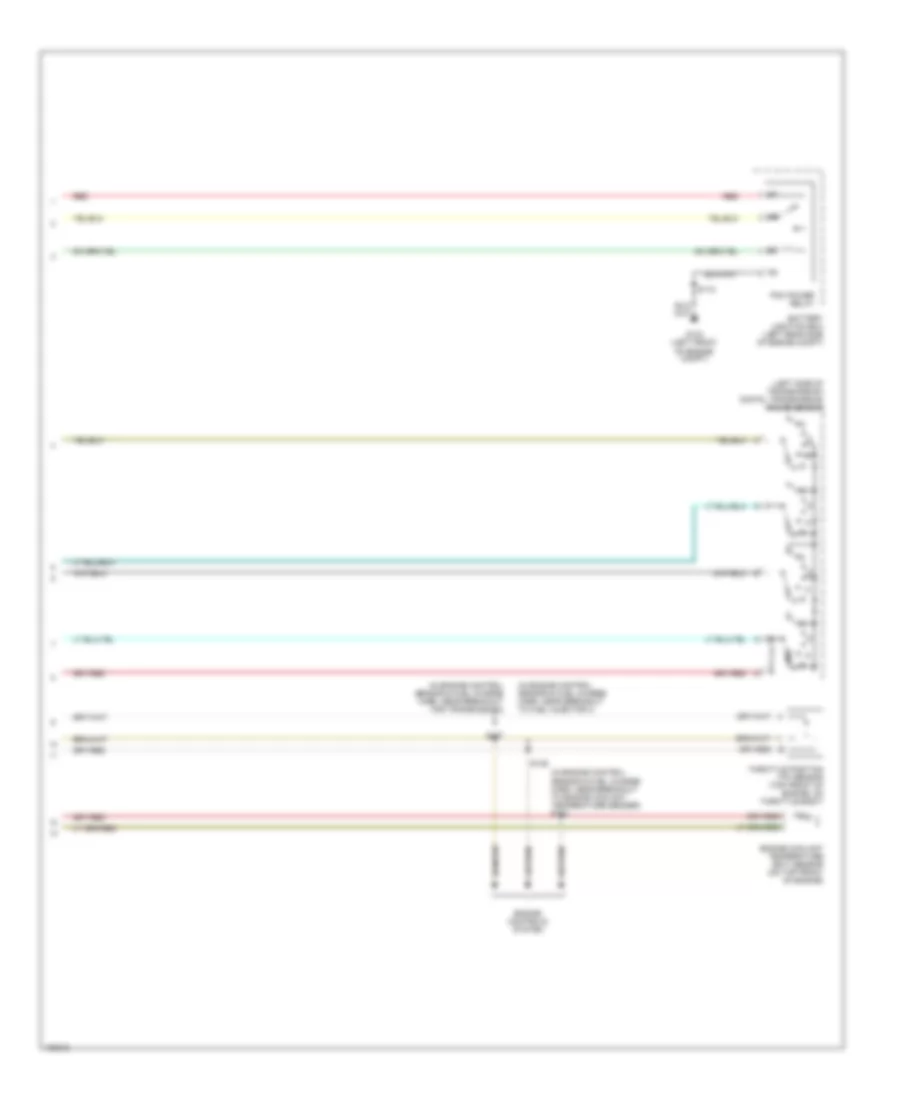
2.3L, A/T Wiring Diagram (2 of 2) for Ford Ranger 2004
List of elements for 2.3L, A/T Wiring Diagram (2 of 2) for Ford Ranger 2004:
- (in engine control sensor & fuel charge harn, near breakout for idle air valve)
- (in engine control sensor & fuel charge harn, near breakout for swirl control solenoid valve)
- (left side of transmission) digital transmission range sensor
- Battery junction box (left rear side of engine compt)
- Cylinder head temperature (cht) sensor (right side of cylinder head)
- Engine controls system
- G104 (left front of engine compt)
- Pcm power relay
- R p
- Red
- S118
- S137
- S151
- S152 (in engine control sensor & fuel charge harn, near breakout for transmission)
- Throttle position (tp) sensor (top right side of engine, on throttle body)
3.0L
3.0L, A/T Wiring Diagram (1 of 2) for Ford Ranger 2004
List of elements for 3.0L, A/T Wiring Diagram (1 of 2) for Ford Ranger 2004:
- (in dash to headlight junction harn, near breakout to battery junction box)
- (in engine control sensor & fuel charge harn, at breakout for powertrain control module)
- (in engine control sensor & fuel charge harn, near breakout for heated oxygen sensor 21)
- (in engine control sensor & fuel charge harn, near breakout for transmission)
- (in engine control sensor & fuel charge harn, near breakout to fuel injector 3)
- 5r44e automatic transmission (left side of transmission)
- Anti-lock brakes system
- Back-up lamps
- Battery junction box (left rear side of engine compt)
- Bpp
- Brake pedal position switch (behind left side of dash, on brake pedal support)
- C175
- C220a
- C220b
- C2280b
- C2280ba
- Cht
- Connector (at bottom of steering column)
- Data link
- Dlc
- Dlc (+)
- Dlc (-)
- Electronic pressure control (epc) solenoid
- Engine controls system
- Epc
- Exterior lights system
- Fuse 10a
- Fuse 15a
- Fuse 30a
- Fuse 5a
- G104 (left front of engine compt)
- G205 (left front of vehicle floor)
- Ground
- Hot at all times
- Hot in run
- Hot in run or start
- Instrument cluster
- Intermediate shaft speed (iss) sensor (left side of trans)
- Iss
- Junction box)
- Malfunction indicator lamp (mil)
- Mil
- Nca
- O/d off
- Oss
- Output shaft speed (oss) sensor (left rear of trans)
- Pcm power diode
- Power
- Powertrain control module (pcm) (right rear of engine compartment, through firewall)
- Prndl
- Ptc 1a
- Red
- S100
- S101
- S104
- S107
- S113
- S117 (in dash to headlight junction harn, near breakout to abs control module)
- S143
- S236
- S237
- Shift solenoids
- Sig rtn
- Smart junction box (behind right side of dash)
- Ss a
- Ss b
- Ss c
- Ss d
- Tcc
- Tcil
- Tcs
- Tft
- Torque converter clutch (tcc) solenoid
- Tr1
- Tr2
- Tr3a
- Tr4
- Transmission control switch (tcs)
- Transmission fluid temperature (tft) sensor
- Tss
- Turbine shaft speed (tss) sensor
- Vbatt
- Vref
3.0L, A/T Wiring Diagram (2 of 2) for Ford Ranger 2004
List of elements for 3.0L, A/T Wiring Diagram (2 of 2) for Ford Ranger 2004:
- (in engine control sensor & fuel charge harn, near breakout for fuel injector 6)
- (in engine control sensor & fuel charge harn, near breakout for transmission)
- (left side of transmission) digital transmission range sensor
- Battery junction box (left rear side of engine compt)
- Engine controls system
- Engine coolant temperature (ect) sensor (on left front of engine near thermostat housing)
- G104 (left front of engine compt)
- Pcm power relay
- R p
- Red
- S118
- S137
- S139
- Throttle position (tp) sensor (top left front of engine, on throttle body)
4.0L
4.0L, A/T Wiring Diagram (1 of 2) for Ford Ranger 2004
List of elements for 4.0L, A/T Wiring Diagram (1 of 2) for Ford Ranger 2004:
- (in dash to headlight junction harn, near breakout to battery junction box)
- (in engine control sensor & fuel charge harn, at breakout for powertrain control module)
- (in engine control sensor & fuel charge harn, near breakout for ignition coil)
- (in engine control sensor & fuel charge harn, near breakout for transmission)
- (in engine control sensor & fuel charge harn, near breakout to fuel injector 3)
- (in engine control sensor & fuel charge harn, near breakout to heated oxygen sensor 11)
- (in engine control sensor & fuel charge harn, near breakout to heated oxygen sensor 12)
- 5r44e automatic transmission (left side of transmission)
- Anti-lock brakes system
- Back-up lamps
- Battery junction box (left rear side of engine compt)
- Bpp
- Brake pedal position switch (behind left side of dash, on brake pedal support)
- C175
- C220a
- C220b
- C2280b
- C2280ba
- Connector (at bottom of steering column)
- Data link
- Dlc
- Dlc (+)
- Dlc (-)
- Ect
- Electronic pressure control (epc) solenoid
- Engine controls system
- Epc
- Exterior lights system
- Fuse 10a
- Fuse 15a
- Fuse 30a
- Fuse 5a
- G104 (left front of engine compt)
- G205 (left front of vehicle floor)
- Ground
- Hot at all times
- Hot in run
- Hot in run or start
- Instrument cluster
- Intermediate shaft speed (iss) sensor (left side of trans)
- Iss
- Junction box)
- Malfunction indicator lamp (mil)
- Mil
- Nca
- O/d off
- Oss
- Output shaft speed (oss) sensor (left rear of trans)
- Pcm power diode
- Power
- Powertrain control module (pcm) (right rear of engine compartment, through firewall)
- Prndl
- Ptc 1a
- Red
- S101
- S104
- S107
- S113
- S117 (in dash to headlight junction harn, near breakout to abs control module)
- S140
- S141
- S143
- S144
- S236
- S237
- Shift solenoids
- Sig rtn
- Smart junction box (behind right side of dash)
- Ss a
- Ss b
- Ss c
- Ss d
- Tcc
- Tcil
- Tcs
- Tft
- Torque converter clutch (tcc) solenoid
- Tr1
- Tr2
- Tr3a
- Tr4
- Transmission control switch (tcs)
- Transmission fluid temperature (tft) sensor
- Tss
- Turbine shaft speed (tss) sensor
- Vbatt
- Vref
4.0L, A/T Wiring Diagram (2 of 2) for Ford Ranger 2004
List of elements for 4.0L, A/T Wiring Diagram (2 of 2) for Ford Ranger 2004:
- (in engine control sensor & fuel charge harn, near breakout for transmission)
- (in engine control sensor & fuel charge harn, near breakout to engine coolant temperature sender) s133
- (in engine control sensor & fuel charge harn, near breakout to fuel injector 4)
- (left side of transmission) digital transmission range sensor
- Battery junction box (left rear side of engine compt)
- Engine controls system
- Engine coolant temperature (ect) sensor (on top front of engine)
- G104 (left front of engine compt)
- Pcm power relay
- R p
- Red
- S118
- S135
- S137
- Throttle position (tp) sensor (top front of engine, on throttle body)

 Čeština
 Dansk
Dansk Deutsch
 Ελληνικά
 English
 English
 Español
 Suomi
Suomi Français
 Français
 עברית
עברית Magyar
 Italiano
 日本語
日本語 한국어
한국어 Nederlands
 Polski
 Português
 Português
 Română
 Русский
 Slovenčina
 Slovenščina
 Svenska
 Türkçe
 中文 (中国)