БЛОК ПРЕДОХРАНИТЕЛЕЙ И РЕЛЕ
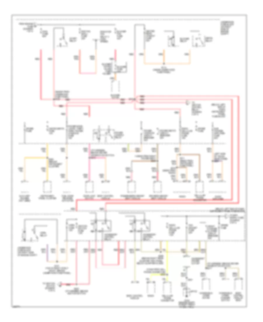
Электросхема блока предохранителей и реле (1 из 4) для Pontiac GTO 2006
 https://portal-diagnostov.com/license.html
Automotive Electricians Portal FZCO
Automotive Electricians Portal FZCO
https://portal-diagnostov.com/license.html
https://portal-diagnostov.com/license.html
Automotive Electricians Portal FZCO
Automotive Electricians Portal FZCO
Электросхема блока предохранителей и реле (1 из 4) для Pontiac GTO 2006 - Список элементов:
- (375mm from right headlamp) s117
- (455mm from left headlamp) s108
- (455mm from left headlamp) s116
- (on right side of engine compt) underhood fuse block
- Abs & tcs control module fuse 25a
- Abs fuse 40a
- Ambient light sensor
- Battery
- Bcm/engine controls fuse 15a
- Body control module
- C1 a
- Cooling fan assembly
- Data link connector (dlc)
- Daytime running lamps relay
- Electronic brake control module (ebcm)
- Engine control module (ecm)
- Engine fuse 60a
- Fog lamp cancel relay
- Fog lamp relay
- From abs fuse (diagram 1 of 4)
- Fuel pump fuse 15a
- Fuel pump relay
- Fusible link
- Generator
- Hazard lamps fuse 15a
- Hazard/ theft indicator relay
- Headlamp relay (high beam)
- Headlamp relay (low beam)
- Interior illumin- ation relay
- Interior illumination fuse 10a
- Left front fog lamp
- Left headlamp
- Left headlamp fuse 20a
- Lighting fuse 60a
- Park lamps fuse 10a
- Park lamps relay
- Powertrain interface module
- Rad fan large fuse 30a
- Radiator fan relay 1 (low speed)
- Radiator fan relay 2 (high speed)
- Radiator fan relay 3 (high speed)
- Red
- Right front fog lamp
- Right headlamp
- Right headlamp fuse 20a
- S100 (inside the under hood fuse panel)
- S102 (inside the under hood fuse panel)
- S105 (295mm from c206)
- S106 (body harness, behind right quarter trim panel, near seat bottom)
- S165 (engine cooling harness, front of battery)
- S215 (330mm from instrument fuse panel)
- Starter
- Stop lamp switch
- Stop lamps fuse 15a
- To engine control relay (diagram 3 of 4)
- To engine fuse (diagram 1 of 4)
- To main fuse (diagram 2 of 4)
- Transmission control module (tcm)
- Underhood fuse block (on right side of engine compt)
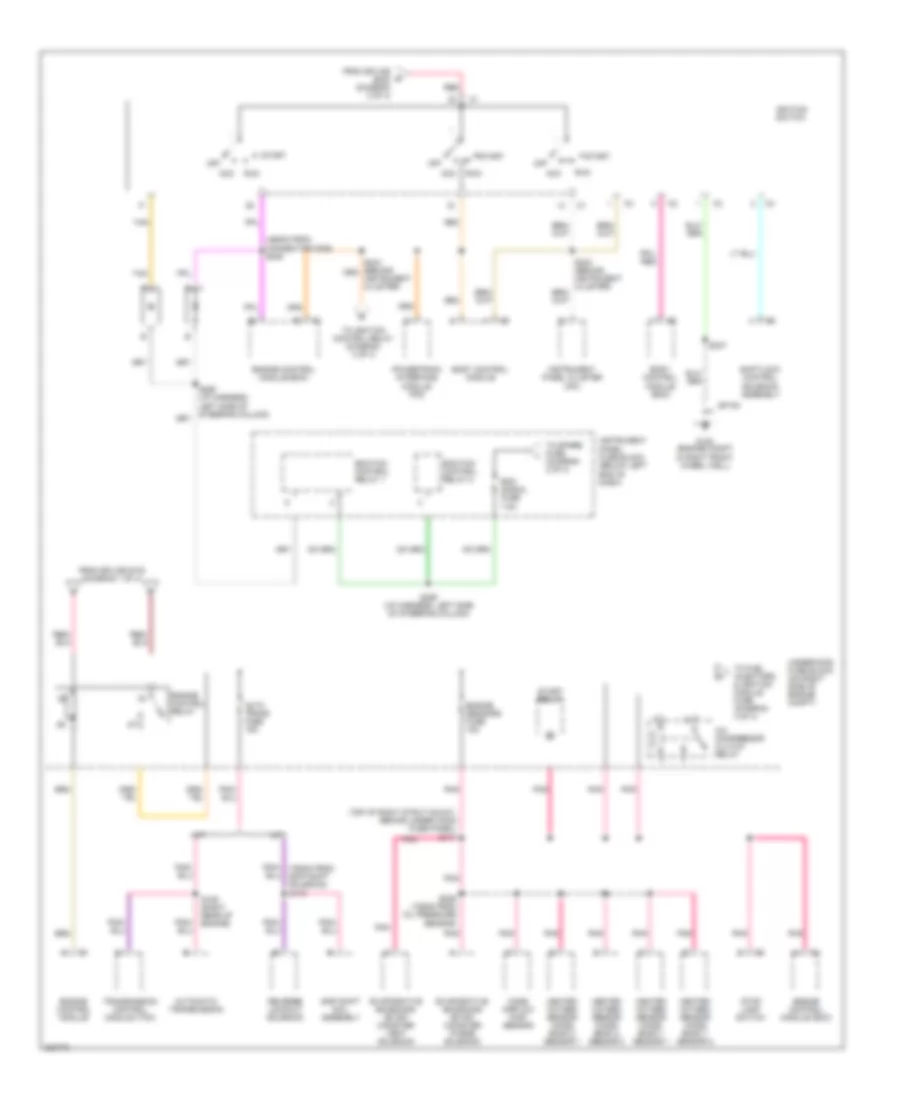
Электросхема блока предохранителей и реле (2 из 4) для Pontiac GTO 2006
Электросхема блока предохранителей и реле (2 из 4) для Pontiac GTO 2006 - Список элементов:
- (1455mm from right power seat) s200
- (2945mm from underhood fuse panel) s103
- (310mm from cell phone connector) s209
- (below left end of dash) instrument panel fuse block
- (i/p harness, behind driver information switch) s210
- (i/p harness, behind driver information switch) s217
- (left side of trunk, near hinge) s267
- Acc socket fuse 20a
- Accessory control relay
- Accessory power outlet
- Audio amplifier
- Auxiliary gauges (not used)
- Blower fan fuse 40a
- Blower fuse 30a
- Blower motor
- Blower motor inline fuse holder
- Blower relay
- Body control module
- Body control module (bcm)
- Cellular phone connector
- Defog relay
- Door lock switch
- Driver's memory seat module
- From engine fuse (diagram 1 of 4)
- Front washer & wiper circuit breaker 20a
- Fuel door release actuator
- G102 (engine compt in right front wheel well)
- Heated rear window fuse 30a
- Horn fuse 15a
- Horn relay
- Ignition switch fuse 7.5a
- Instrument panel cluster
- Instruments fuse 10a
- Main fuse 60a
- Passenger's memory seat module
- Power door locks, theft, horn, power windows fuse 15a
- Power seats circuit breaker 20a
- Power window relay
- Power windows circuit breaker 20a
- Rad fan small fuse 30a
- Radiator fan relay 3 (high speed)
- Radio
- Radio cellular phone fuse 7.5a
- Radio, cellular phone fuse 15a
- Red
- S104
- S114 (inside under hood fuse panel)
- S121 (top of right strut mount, behind under hood fuse panel)
- S202 (i/p harness, behind ignition switch)
- S211 (665mm from instrument fuse panel)
- S216 (555mm from radio)
- S241
- S293 (behind instrument cluster)
- S295 (behind right rear quarter trim panel, below quarter glass)
- Sp100
- Spare fuse
- Start relay
- Sub woofer amplifier fuse 20a
- To ecm signal fuse (diagram 3 of 4)
- To ignition control relay (diagram 4 of 4)
- To ignition switch (diagram 3 of 4)
- Underhood fuse block (on right side of engine compt)
- Windshield wiper motor
- Windshield wiper/ washer switch
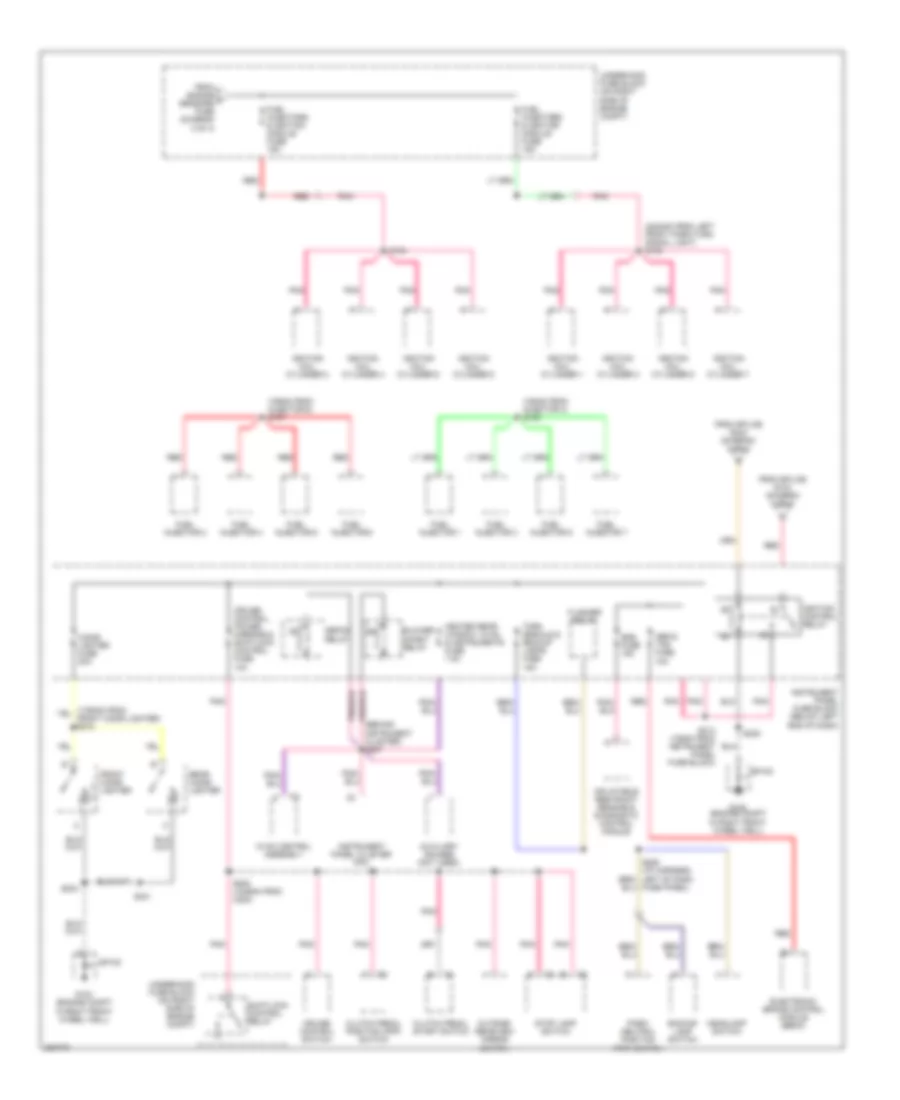
Электросхема блока предохранителей и реле (3 из 4) для Pontiac GTO 2006
Электросхема блока предохранителей и реле (3 из 4) для Pontiac GTO 2006 - Список элементов:
- (490mm from connector c206) s245
- (top of right strut mount, behind under hood fuse panel) s111
- A/c compressor clutch relay
- A/t
- Acc
- Auto trans fuse 15a
- Automatic transmission
- Body control module
- Body control module (bcm)
- Ecm signal fuse 7.5a
- Ecm/tcm control relay 1
- Ecm/tcm control relay 2
- Engine control module
- Engine control module (ecm)
- Engine control relay
- Engine sensors fuse 15a
- Evaporative emissions (evap) canister purge solenoid
- Evaporative emissions (evap) canister vent solenoid
- From splice s102 (diagram 1 of 4)
- From splice s202 (diagram 2 of 4)
- G102 (engine compt in right front wheel well)
- Heated oxygen sensor (ho2s) bank 1 sensor 1
- Heated oxygen sensor (ho2s) bank 1 sensor 2
- Heated oxygen sensor (ho2s) bank 2 sensor 1
- Heated oxygen sensor (ho2s) bank 2 sensor 2
- Ignition switch
- Instrument cluster)
- Instrument panel cluster (ipc)
- Instrument panel fuse block (below left end of dash)
- M/t
- Mass airflow (maf) sensor
- Off
- Pnk
- Pnk/ (750mm from skip shift solenoid) s110
- Powertrain interface module (pim)
- Red
- Reverse lockout solenoid
- Run
- S109 (right rear of engine)
- S237
- S246 (105mm from oil pressure sensor)
- S289 (i/p harness, left side of steering column)
- S290 (i/p harness, left side of steering column)
- Shiftlock control solenoid assembly
- Skip shift coil assembly
- Sp100
- Start
- Start relay
- Stop lamp switch
- Tan
- To fuel injectors & ignition module fuse (diagram 4 of 4)
- To ignition control relay (diagram 4 of 4)
- To spare fuse (diagram 2 of 4)
- Transmission control module (tcm)
- Underhood fuse block (on right side of engine compt)
Электросхема блока предохранителей и реле (4 из 4) для Pontiac GTO 2006
Электросхема блока предохранителей и реле (4 из 4) для Pontiac GTO 2006 - Список элементов:
- (150mm from injector 3) s138
- (155mm from injector 6) s137
- (2240mm from left front park/turn signal light) s155
- (behind instrument cluster) s207
- Abs & tcs fuse 10a
- Auxiliary gauges (not used)
- Backup lamp switch
- Blower inhibit relay
- Cigar lighter fuse 20a
- Clutch pedal position (cpp) switch
- Clutch pedal start switch
- Cruise control switch
- Cruise control, power mirrors & shiftlock control fuse 10a
- Defog relay
- Electronic brake control module (ebcm)
- Flasher relay
- From engine f sensors fuse (diagram 3 of 4)
- From splice s104 (diagram 2 of 4)
- From splice s244 (diagram 3 of 4)
- Front cigar lighter
- Fuel injector 1
- Fuel injector 2
- Fuel injector 3
- Fuel injector 4
- Fuel injector 5
- Fuel injector 6
- Fuel injector 7
- Fuel injector 8
- Fuel injectors & ignition module fuse 15a
- Fuse panel)
- G102 (engine compt in right front wheel well)
- Headlamp switch
- Heated rear window, hvac & instruments fuse 7.5a
- Hvac control assembly
- Ignition coil cylinder 1
- Ignition coil cylinder 2
- Ignition coil cylinder 3
- Ignition coil cylinder 4
- Ignition coil cylinder 5
- Ignition coil cylinder 6
- Ignition coil cylinder 7
- Ignition coil cylinder 8
- Ignition control relay
- Inflatable restraint sensing & diagnostic control module
- Instrument panel cluster (ipc)
- Instrument panel fuse block (below left end of dash)
- Outside rearview mirror switch
- Park/ neutral position (pnp) switch
- Pnk
- Rear cigar lighter
- Red
- S154
- S208 (1245mm from c200)
- S213 (105mm from instrument panel fuse block)
- S234
- S238
- S241
- Shiftlock control relay
- Sp100
- Srs fuse 15a
- Stop lamp switch
- Turn signals & backup lamps fuse 15a
- Underhood fuse block (on right side of engine compt)

 Čeština
 Dansk
Dansk Deutsch
 Ελληνικά
 English
 English
 Español
 Suomi
Suomi Français
 Français
 עברית
עברית Magyar
 Italiano
 日本語
日本語 한국어
한국어 Nederlands
 Polski
 Português
 Português
 Română
 Русский
 Slovenčina
 Slovenščina
 Svenska
 Türkçe
 中文 (中国)