СИСТЕМА КОНДИЦИОНЕРА
2.0L ВИН П.
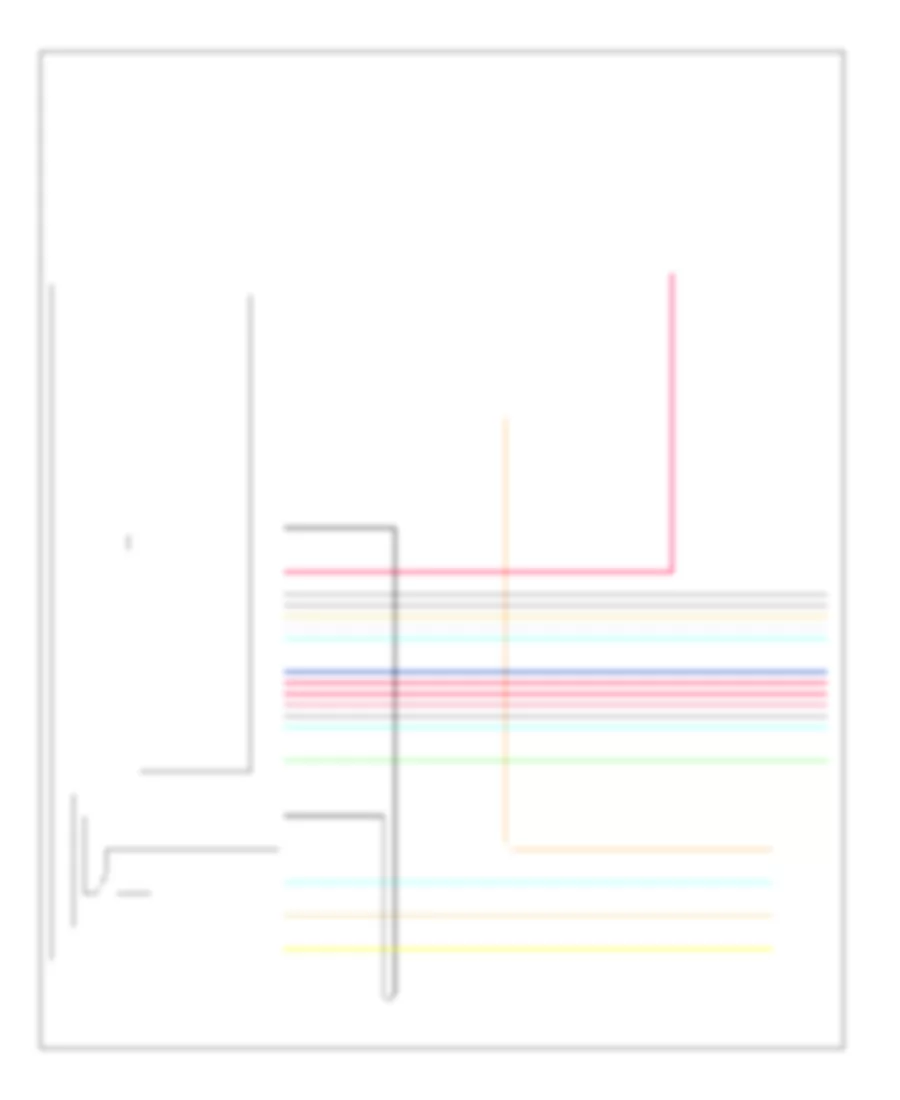
2.0L ВИН П, Электросхема компрессора для Pontiac G5 GT 2007
 https://portal-diagnostov.com/license.html
Automotive Electricians Portal FZCO
Automotive Electricians Portal FZCO
https://portal-diagnostov.com/license.html
https://portal-diagnostov.com/license.html
Automotive Electricians Portal FZCO
Automotive Electricians Portal FZCO
2.0L ВИН П, Электросхема компрессора для Pontiac G5 GT 2007 - Список элементов:
- 5v ref
- A/c clutch fuse 10a
- A/c clutch relay
- A/c compressor clutch (lower left, front of engine, below generator)
- A/c compressor clutch diode
- A/c refrigerant pressure sensor (in right front of engine compt, on a/c line, near compressor)
- A/c req sig
- A/c request indicator
- A/c request sig
- A/c request switch
- Batt
- Body control module (bcm) (under center dash, on right side of center console)
- C3 f2
- C5 a4
- Computer data lines system
- Ect sig
- Engine coolant temperature (ect) sensor (top front, left side of engine, near camshaft cover)
- G101 (left side of engine compt, under coolant reservoir)
- G203 (behind right side of dash)
- Gnd
- Hot at all times
- Hot in run or start
- Hot w/ run/ crank relay energized
- Hvac control module (center of dash, below radio)
- Hvac/ ip ign fuse 10a
- Hvac/pk3 + fuse 10a
- Ign 1 voltage
- Logic
- Low ref
- Pnk
- Power distribution system
- Powertrain control module (pcm) (left side of engine compt, near coolant reservoir)
- Press sens sig
- Rly ctrl
- Serial data
- Tan
- Underhood fuse block (in engine compt, next to left strut tower)
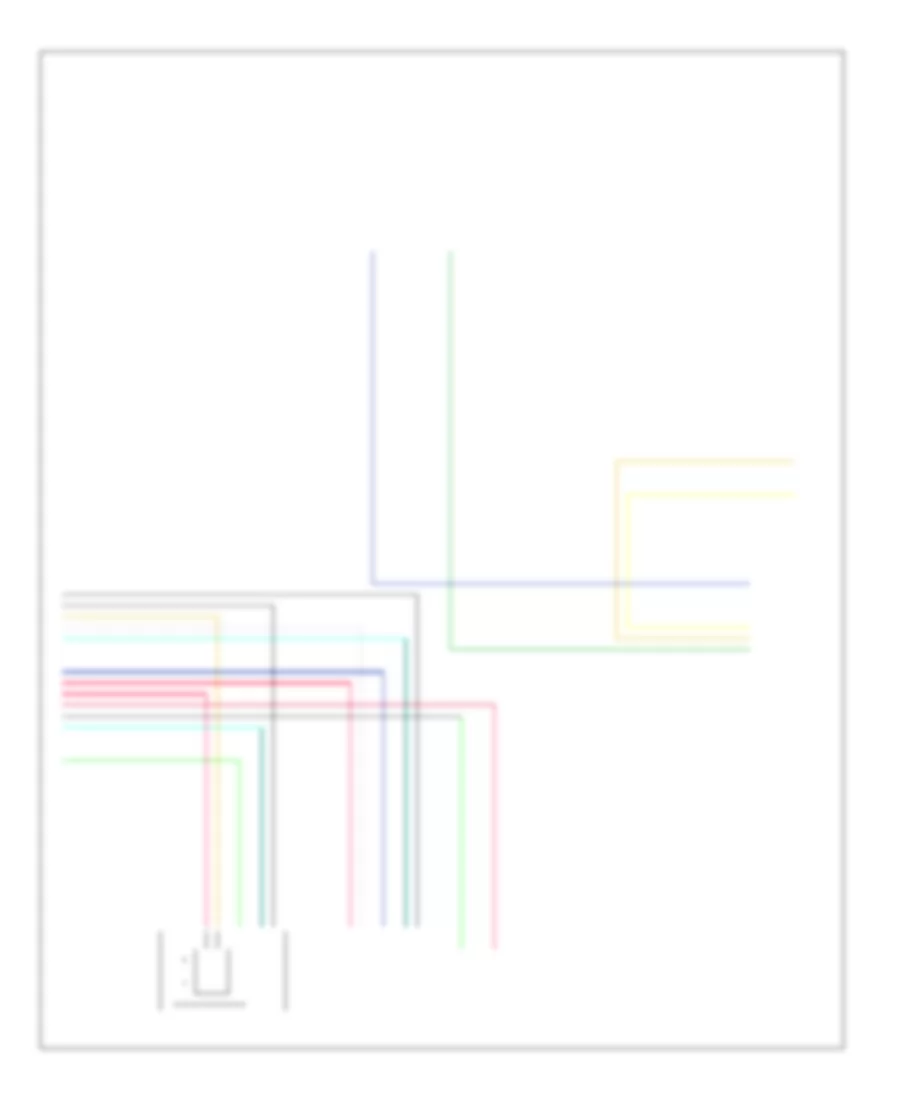
2.0L ВИН П, Электросхема кондиционера с ручный управлением (1 из 2) для Pontiac G5 GT 2007
2.0L ВИН П, Электросхема кондиционера с ручный управлением (1 из 2) для Pontiac G5 GT 2007 - Список элементов:
- (in hvac jumper harness, approximately 4.9 cm (2 in) from hvac control assembly) s261
- 5 volt ref
- A/c req sig
- A/c request indicator
- A/c request sig
- A/c request switch
- Air temp dr cntrl
- Air temp dr pos
- Batt
- Bcm 3 fuse 30a
- Blower motor (under right side of dash)
- Blower motor resistor (under right side of dash, next to blower motor)
- Blower motor switch
- Body control module (bcm) (under center dash, on right side of center console)
- C4 c2
- Close recir door
- Computer data lines system
- Defogger system
- Fresh air indicator
- G203 (behind right side of dash)
- Gnd
- Ground
- High
- Hot at all times
- Hot w/ run/ crank relay energized
- Hvac control module (center of dash, below radio)
- Hvac relay
- Hvac/ ip ign fuse 10a
- Hvac/pk3 + fuse 10a
- Ign 1 voltage
- Interior lights system
- Logic
- Low
- Mode door cntrl
- Mode door position sig
- Mode switch
- Off
- Open recir door
- Pnk
- Power distribution system
- R defog relay cntrl
- R defog switch sig
- Recir- culation indicator
- Recir- culation switch
- Run/ crank relay control
- Serial data
- Tan
- Temperature control switch
- Underhood fuse block (in engine compt, next to left strut tower)
2.0L ВИН П, Электросхема кондиционера с ручный управлением (2 из 2) для Pontiac G5 GT 2007
2.0L ВИН П, Электросхема кондиционера с ручный управлением (2 из 2) для Pontiac G5 GT 2007 - Список элементов:
- 5v ref
- A/c cltch fuse 10a
- A/c clutch relay
- A/c compressor clutch (lower left, front of engine, below generator)
- A/c compressor clutch diode
- A/c refrigerant pressure sensor (in right front of engine compt, on a/c line, near compressor)
- A1 c5
- A11
- Air temperature actuator (center of dash, left side of hvac module)
- C5 a4
- Computer data lines system
- Cool ser/par relay
- Cooling fan 1 (front of engine compt, attached to left of radiator)
- Cooling fan 1 fuse 30a
- Cooling fan 1 relay
- Cooling fan 2 (front of engine compt, attached to right of radiator)
- Cooling fan 2 fuse 30a
- Cooling fan 2 relay
- E10
- Ect sig
- Engine coolant temperature (ect) sensor (top front, left side of engine, near camshaft cover)
- F10
- F2 c3
- G101 (left side of engine compt, under coolant reservoir)
- G111 (front of engine compt, near cooling fans)
- Hot at all times
- Hot in run or start
- Low ref
- Mode actuator (center of dash, left side of hvac module)
- Pnk
- Powertrain control module (pcm) (left side of engine compt, near coolant reservoir)
- Press sens sig
- Recirculation actuator (right side of dash, above blower motor)
- Rly ctrl
- Serial data
- Tan
- Underhood fuse block (in engine compt, next to left strut tower)
2.2L ВИН Ф.
2.2L ВИН Ф, Электросхема компрессора для Pontiac G5 GT 2007
2.2L ВИН Ф, Электросхема компрессора для Pontiac G5 GT 2007 - Список элементов:
- 5v ref
- A/c clutch fuse 10a
- A/c clutch relay
- A/c compressor clutch (left front of engine)
- A/c compressor clutch diode
- A/c refrigerant pressure sensor (in right front of engine compt, on a/c line, near compressor)
- A/c req sig
- A/c request indicator
- A/c request sig
- A/c request switch
- Batt
- Body control module (bcm) (under center dash, on right side of center console)
- C3 f2
- C5 a4
- Computer data lines system
- Ect sig
- Engine control module (ecm) (left side of engine compt, in front of underhood fuse block)
- Engine coolant temperature (ect) sensor (rear of engine, near exhaust manifold)
- G101 (left side of engine compt, under coolant reservoir)
- G203 (behind right side of dash)
- Gnd
- Hot at all times
- Hot in run or start
- Hot w/ run/ crank relay energized
- Hvac control module (center of dash, below radio)
- Hvac/ ip ign fuse 10a
- Hvac/pk3 + fuse 10a
- Ign 1 voltage
- Logic
- Low ref
- Pnk
- Power distribution system
- Press sens sig
- Rly ctrl
- Serial data
- Tan
- Underhood fuse block (in engine compt, next to left strut tower)
2.2L ВИН Ф, Электросхема кондиционера с ручный управлением (1 из 2) для Pontiac G5 GT 2007
2.2L ВИН Ф, Электросхема кондиционера с ручный управлением (1 из 2) для Pontiac G5 GT 2007 - Список элементов:
- (in hvac jumper harness, approximately 4.9 cm (2 in) from hvac control assembly) s261
- 5 volt ref
- A/c req sig
- A/c request indicator
- A/c request sig
- A/c request switch
- Air temp dr cntrl
- Air temp dr pos
- Batt
- Bcm 3 fuse 30a
- Blower motor (under right side of dash)
- Blower motor resistor (under right side of dash, next to blower motor)
- Blower motor switch
- Body control module (bcm) (under center dash, on right side of center console)
- C4 c2
- Close recir door
- Computer data lines system
- Defogger system
- Fresh air indicator
- G203 (behind right side of dash)
- Gnd
- Ground
- High
- Hot at all times
- Hot w/ run/ crank relay energized
- Hvac control module (center of dash, below radio)
- Hvac relay
- Hvac/ ip ign fuse 10a
- Hvac/pk3 + fuse 10a
- Ign 1 voltage
- Interior lights system
- Logic
- Low
- Mode door cntrl
- Mode door pos sig
- Mode switch
- Off
- Open recir door
- Pnk
- Power distribution system
- R defog relay cntrl
- R defog switch sig
- Recir- culation indicator
- Recir- culation switch
- Run/ crank relay control
- Serial data
- Tan
- Temperature control switch
- Underhood fuse block (in engine compt, next to left strut tower)
2.2L ВИН Ф, Электросхема кондиционера с ручный управлением (2 из 2) для Pontiac G5 GT 2007
2.2L ВИН Ф, Электросхема кондиционера с ручный управлением (2 из 2) для Pontiac G5 GT 2007 - Список элементов:
- 5v ref
- A/c cltch fuse 10a
- A/c clutch relay
- A/c compressor clutch (left front of engine)
- A/c compressor clutch diode
- A/c refrigerant pressure sensor (right front of engine compt, on a/c line, near compressor)
- A1 c5
- A11
- Air temperature actuator (center of dash, left side of hvac module)
- C3 f2
- C5 a4
- Computer data lines system
- Cooling fan 1 fuse 30a
- Cooling fan 1 relay
- Cooling fan 2 fuse 30a
- Cooling fan 2 relay
- Cooling fan diode
- Cooling fan motor
- E10
- Ect sig
- Engine control module (ecm) (left side of engine compt, in front of underhood fuse block)
- Engine coolant temperature (ect) sensor (rear of engine, near exhaust manifold)
- F10
- G101 (left side of engine compt, under coolant reservoir)
- G111 (front of engine compt, near cooling fans)
- Hot at all times
- Hot in run or start
- Low ref
- Mode actuator (center of dash, left side of hvac module)
- Pnk
- Press sens sig
- Recirculation actuator (right side of dash, above blower motor)
- Rly ctrl
- S105
- S110
- Serial data
- Tan
- Underhood fuse block (in engine compt, next to left strut tower)
2.4L ВИН Б.
2.4L ВИН Б, Электросхема компрессора для Pontiac G5 GT 2007
2.4L ВИН Б, Электросхема компрессора для Pontiac G5 GT 2007 - Список элементов:
- 5v ref
- A/c cltch fuse 10a
- A/c clutch relay
- A/c compressor clutch (left front of engine)
- A/c compressor clutch diode
- A/c refrigerant pressure sensor (right front of engine compt, on a/c line, near compressor)
- A/c req sig
- A/c request indicator
- A/c request sig
- A/c request switch
- A4 c5
- Batt
- Body control module (bcm) (under center dash, on right side of center console)
- C3 f2
- Computer data lines system
- Ect sig
- Engine control module (ecm) (left side of engine compt, in front of underhood fuse block)
- Engine coolant temperature (ect) sensor (rear, left side of engine, below exhaust)
- G101 (left side of engine compt, under coolant reservoir)
- G203 (behind right side of dash)
- Gnd
- Hot at all times
- Hot in run or start
- Hot w/ run/ crank relay energized
- Hvac control module (center of dash, below radio)
- Hvac/ ip ign fuse 10a
- Hvac/pk3 fuse 10a
- Ign 1 voltage
- Logic
- Low ref
- Pnk
- Power distribution system
- Press sens sig
- Rly ctrl
- Serial data
- Tan
- Underhood fuse block (in engine compt, next to left strut tower)
2.4L ВИН Б, Электросхема кондиционера с ручный управлением (1 из 2) для Pontiac G5 GT 2007
2.4L ВИН Б, Электросхема кондиционера с ручный управлением (1 из 2) для Pontiac G5 GT 2007 - Список элементов:
- (in hvac jumper harness, approximately 4.9 cm (2 in) from hvac control assembly) s261
- 5 volt ref
- A/c req sig
- A/c request indicator
- A/c request sig
- A/c request switch
- Air temp dr cntrl
- Air temp dr pos
- Batt
- Bcm 3 fuse 30a
- Blower motor (under right side of dash)
- Blower motor resistor (under right side of dash, next to blower motor)
- Blower motor switch
- Body control module (bcm) (under center dash, on right side of center console)
- C2 c4
- Close recir door
- Computer data lines system
- Defogger system
- Fresh air indicator
- G203 (behind right side of dash)
- Gnd
- Ground
- High
- Hot at all times
- Hot w/ run/ crank relay energized
- Hvac control module (center of dash, below radio)
- Hvac relay
- Hvac/ ip ign fuse 10a
- Hvac/pk3 + fuse 10a
- Ign 1 voltage
- Interior lights system
- Logic
- Low
- Mode door cntrl
- Mode door pos sig
- Mode switch
- Off
- Open recir door
- Pnk
- Power distribution system
- R defog relay cntrl
- R defog switch sig
- Recir- culation indicator
- Recir- culation switch
- Run/ crank relay control
- Serial data
- Tan
- Temperature control switch
- Underhood fuse block (in engine compt, next to left strut tower)
2.4L ВИН Б, Электросхема кондиционера с ручный управлением (2 из 2) для Pontiac G5 GT 2007
2.4L ВИН Б, Электросхема кондиционера с ручный управлением (2 из 2) для Pontiac G5 GT 2007 - Список элементов:
- 5v ref
- A/c cltch fuse 10a
- A/c cltch relay
- A/c compressor clutch (left front of engine)
- A/c compressor clutch diode
- A/c refrigerant pressure sensor (right front of engine compt, on a/c line, near compressor)
- A11
- A4 c5
- Air temperature actuator (center of dash, left side of hvac module)
- Computer data lines system
- Cool ser/par relay
- Cooling fan 1 fuse 30a
- Cooling fan 1 relay
- Cooling fan 2 fuse 30a
- Cooling fan 2 relay
- Cooling fan motor
- Cooling fan resistor
- E10
- Ect sig
- Engine control module (ecm) (left side of engine compt, in front of underhood fuse block)
- Engine coolant temperature (ect) sensor (rear, left side of engine, below exhaust)
- F10
- F2 c3
- G101 (in left side of engine compt, under coolant reservoir)
- G111 (front of engine compt, near cooling fans)
- Hot at all times
- Hot in run or start
- Low ref
- Mode actuator (center of dash, left side of hvac module)
- Pnk
- Press sens sig
- Recirculation actuator (right side of dash, above blower motor)
- Rly ctrl
- Serial data
- Tan
- Underhood fuse block (in engine compt, next to left strut tower)

 Čeština
 Dansk
Dansk Deutsch
 Ελληνικά
 English
 English
 Español
 Suomi
Suomi Français
 Français
 עברית
עברית Magyar
 Italiano
 日本語
日本語 한국어
한국어 Nederlands
 Polski
 Português
 Português
 Română
 Русский
 Slovenčina
 Slovenščina
 Svenska
 Türkçe
 中文 (中国)