POWER TOP/SUNROOF
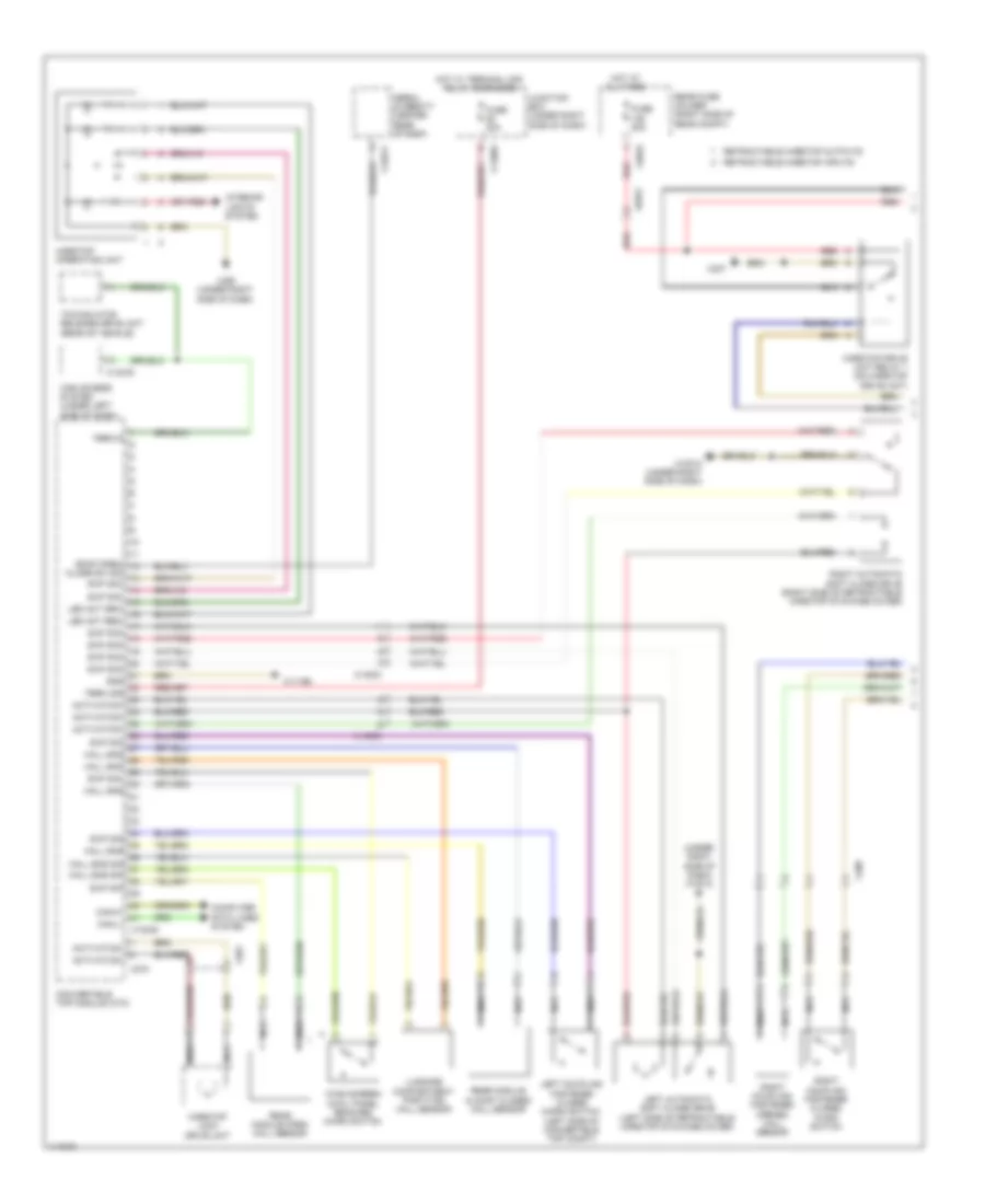
Convertible Top Wiring Diagram (1 of 2) for BMW M3 2013

List of elements for Convertible Top Wiring Diagram (1 of 2) for BMW M3 2013:
- (under right side of dash) x10012
- Activation-
- Aerial diversity (center rear of roof)
- Can-h-
- Can-l-
- Car access system (under left side of dash)
- Close sw sig
- Computer data lines system
- Convertible top module (ctm)
- Fuse 20a
- Fuse 50a
- Gnd
- Hall sns
- Hall sns sig
- Hardtop drive unit relay 1 (on hardtop drive unit)
- Hardtop lock drive unit
- Hardtop operating unit
- Hot at all times
- Hot w/ terminal 30g relay energized
- Interior lights system
- Junction box (under right side of dash)
- Led act red-
- Left automatic soft close drive (left side of retractable hardtop stowage cover)
- Left coupling fastener closed micro switch (left side of convertible top compt)
- Luggage compartment partition hall sensor
- Nca
- Rear fuse holder (right side of rear compt)
- Rear module almost closed hall sensor
- Rear module open hall sensor
- Red
- Retractable hardtop inputs
- Retractable hardtop outputs
- Right automatic soft close drive (right side of retractable hardtop stowage cover)
- Right coupling fastener closed micro switch
- Right coupling fastener opened hall sensor
- Roof open/
- Swf sig
- Swf sig-
- Term 30g
- Term15
- Towing hitch release drive unit (rear of vehicle)
- Wind screen cowl panel reached micro switch
- X10012 (under right side of dash)
- X11003
- X11166
- X13039
- X13376
- X13911
- X14303
- X201
- X270
- X327
- X3670
- X400
- X490 (under right side of dash)
- X6975
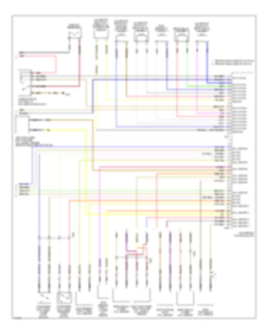
Convertible Top Wiring Diagram (2 of 2) for BMW M3 2013
List of elements for Convertible Top Wiring Diagram (2 of 2) for BMW M3 2013:
- (in hardtop drive unit) coupling fastener valve
- (in hardtop drive unit) hydraulic oil temperature sensor
- (in hardtop drive unit) rear module valve 1
- (in hardtop drive unit) rear module valve 3
- Activation+
- Activation-
- Convertible top module (ctm)
- Hall sns sig
- Hall sns sply
- Hardtop drive unit
- Hardtop drive unit relay 2 (on hardtop drive unit)
- Left positioned roof package hall effect sensor (retractable hardtop inputs)
- Nca
- Rear module closed hall sensor
- Rear module valve 2
- Red
- Retractable hardtop inputs
- Retractable hardtop outputs
- Right positioned roof package hall effect sensor
- Roof package down hall sensor
- Roof package up hall sensor
- Roof segment partly closed hall sensor
- Roof segment partly open hall sensor
- Roof segments valve
- Sw sig
- Tem sig -
- Temp sig
- Windscreen cowl panel locked micro switch
- Windscreen cowl panel released micro switch
- X200
- X201
- X310
- X327
- X410
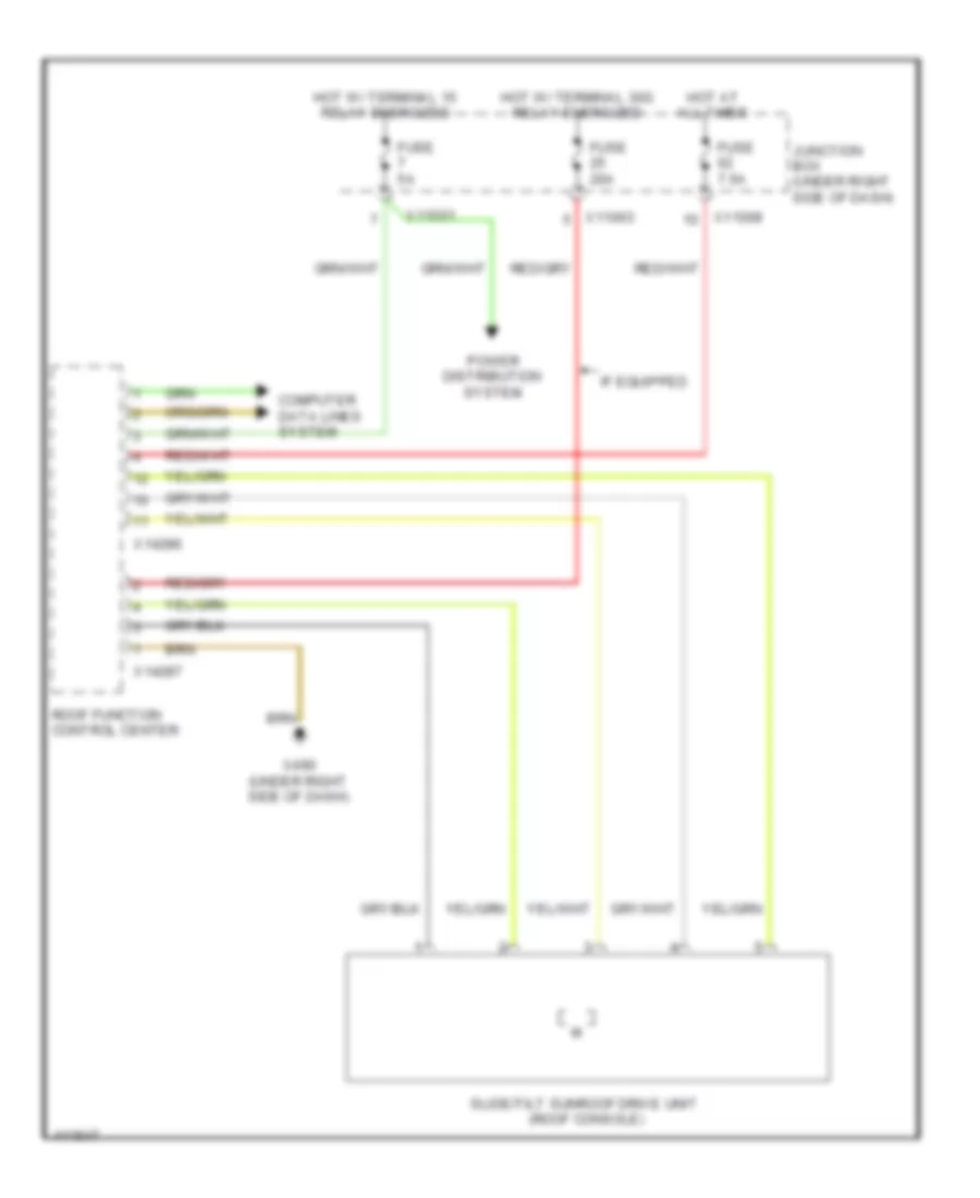
Sunroof Wiring Diagram for BMW M3 2013
List of elements for Sunroof Wiring Diagram for BMW M3 2013:
- Computer data lines system
- Fuse 20a
- Fuse 5a
- Fuse 7.5a
- Hot at all times
- Hot w/ terminal 15 relay energized
- Hot w/ terminal 30g relay energized
- If equipped
- Junction box (under right side of dash)
- Power distribution system
- Roof function control center
- Slide/tilt sunroof drive unit (roof console)
- X11001
- X11003
- X11008
- X14286
- X14287
- X490 (under right side of dash)
STARTING/CHARGINGSHIFT INTERLOCKTRANSMISSIONSUPPLEMENTAL RESTRAINTSAIR CONDITIONINGANTI-LOCK BRAKESBODY CONTROL MODULESWARNING SYSTEMSACTIVE BODYWORKSCRUISE CONTROLTRUNK, TAILGATE, FUEL DOORCOOLING FANANTI-THEFTCOMPUTER DATA LINESELECTRONIC POWER STEERINGDEFOGGERSENGINE PERFORMANCEGROUND DISTRIBUTIONELECTRONIC SUSPENSIONHORNINSTRUMENT CLUSTEREXTERIOR LIGHTSHEADLIGHTSINTERIOR LIGHTSPASSIVE RESTRAINTSMEMORY SYSTEMSPOWER WINDOWSPOWER MIRRORSNAVIGATIONPOWER TOP/SUNROOFPOWER DISTRIBUTIONPOWER SEATSPOWER DOOR LOCKSRADIO