
 Čeština
 Dansk
Dansk Deutsch
 Ελληνικά
 English
 English
 Español
 Suomi
Suomi Français
 Français
 עברית
עברית Magyar
 Italiano
 日本語
日本語 한국어
한국어 Nederlands
 Polski
 Português
 Português
 Română
 Русский
 Slovenčina
 Slovenščina
 Svenska
 Türkçe
 中文 (中国)

ELECTRONIC POWER STEERING
Electronic Power Steering Wiring Diagram for Volvo XC90 2004
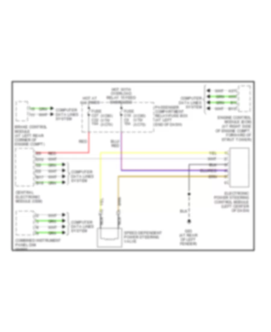

List of elements for Electronic Power Steering Wiring Diagram for Volvo XC90 2004:
- (xc90) (v70/ (xc70)
- A37
- A55
- B13
- B17
- B18
- Brake control module (at left rear corner of engine compt)
- Central electronic module (cem)
- Combined instrument panel dim
- Computer data lines system
- D10
- Electronic power steering control module (left center of dash)
- Engine control module (ecm) (at right side of engine compt, forward of strut tower)
- Fuse c16 c5 15a
- Fuse c27 c32 10a
- G93 (at rear of left fender)
- Hot at all times
- Hot with overload relay 15 feed energized
- Nca
- Passenger compartment relay/fuse box (at left end of dash)
- Red
- Speed dependent power steering valve
AIR CONDITIONINGANTI-LOCK BRAKESCRUISE CONTROLANTI-THEFTCOOLING FANCOMPUTER DATA LINESELECTRONIC POWER STEERINGGROUND DISTRIBUTIONDEFOGGERSEXTERIOR LIGHTSENGINE PERFORMANCEINTERIOR LIGHTSHEADLIGHTSINSTRUMENT CLUSTERMEMORY SYSTEMSHORNNAVIGATIONPOWER DISTRIBUTIONPOWER TOP/SUNROOFPOWER DOOR LOCKSPOWER MIRRORSPOWER SEATSSHIFT INTERLOCKSTARTING/CHARGINGPOWER WINDOWSRADIOTRANSMISSIONWARNING SYSTEMSSUPPLEMENTAL RESTRAINTSWIPER/WASHERBODY CONTROL MODULES