ENGINE PERFORMANCE
4.2L
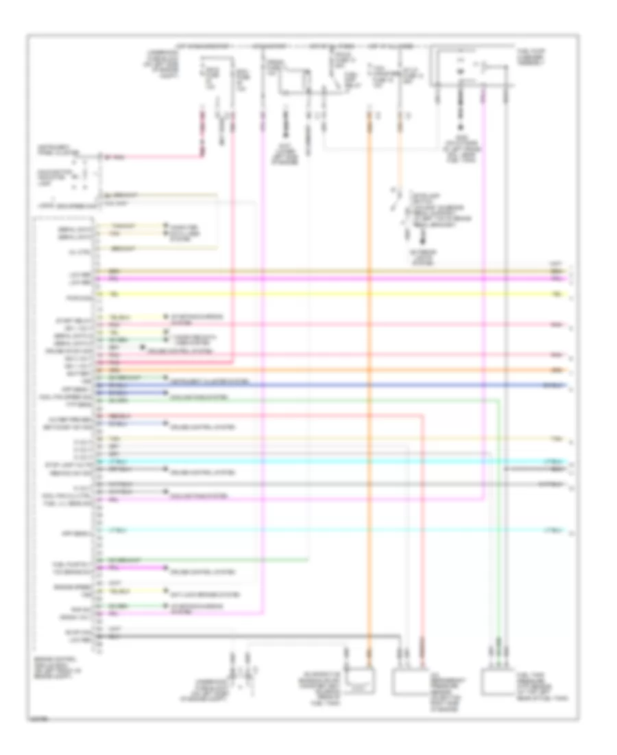
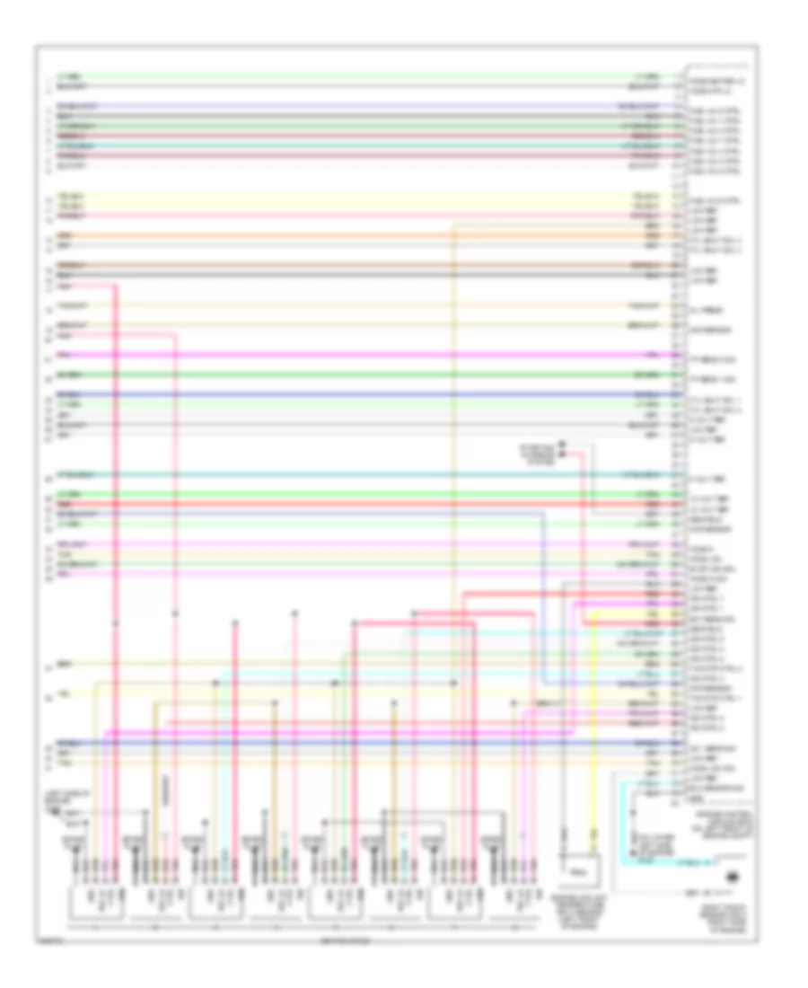
4.2L, Engine Performance Wiring Diagram (1 of 5) for Isuzu Ascender Limited 2005


List of elements for 4.2L, Engine Performance Wiring Diagram (1 of 5) for Isuzu Ascender Limited 2005:
- start enable rly
- (on lower left side of engine) g107
- 4wd low sig
- 5 volt ref
- A/c compr rel
- A/c press sens
- Accelerator pedal position (app) sensor (w/ eap: under left side of i/p) (w/o eap: on accelerator bracket)
- Air conditioning system
- Air fuse 56 60a
- Air pump relay
- Air sol fuse 54 15a
- Air sol relay
- Anti lock brakes system
- App sens 1 sig
- App sens 2 sig
- B10
- Battery
- Body control module (bcm) (beneath left rear seat, on rear fuse block)
- Cc on sw input
- Cls 2 data
- Cool fan clutch
- Cooling fan sp
- Cooling fans system
- Crank req sig
- Crank voltage
- Cruise control system
- Cruise control system transmissions system
- D11
- Data link connector (below dash, above accelerator pedal)
- E11
- Eng spd sig out
- Etc/tcc brk sig
- F14
- Fuel lvl sens sig
- Fuel tank press
- Fuel tank pressure sensor (at top left rear of fuel tank)
- G305 (on outside of left frame rail, near fuel tank)
- Hot at all times
- Hot in acc, run or start
- Hot in run or start
- Iat sens sig
- Ign 0 fuse 47 10a
- Ign 0 input
- Ign 1 volt
- Ign e fuse 22 10a
- Instrument cluster system
- Instrument panel cluster
- Intake air temperature (iat) sensor (in air intake duct,
- Lo ref
- Low ref
- Malfunction indicator lamp
- Mil ctrl
- On top right of engine)
- Pcm b fuse 10 20a
- Pnk
- Powertrain control module (pcm) (on left front of engine)
- Rear fuse block (below left rear seat)
- Red
- Res/acc sw
- Secondary air injection (air) pump (on left frame rail, near ebcm)
- Secondary air injection (air) pump relay (on left frame rail, near ebcm)
- Secondary air injection (air) solenoid
- Set/cruise sw
- Sp205 (below left side of i/p)
- Starting/ charging system
- Stop lamp volt
- Stoplamp switch (w/o eap: on brake pedal support) (w/ eap: top of brake pedal bracket)
- Tan
- Underhood fuse block (on left side of engine compartment)
- Vss
- Vss signal out
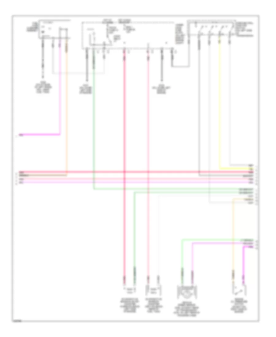
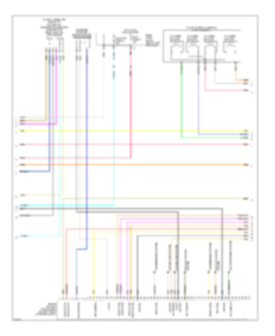
4.2L, Engine Performance Wiring Diagram (2 of 5) for Isuzu Ascender Limited 2005
List of elements for 4.2L, Engine Performance Wiring Diagram (2 of 5) for Isuzu Ascender Limited 2005:
- A11
- Eng 1 fuse 26 10a
- Engine oil pressure switch (on bottom right side of engine)
- Evaporative emission (evap) canister purge solenoid (left side of engine)
- Evaporative emission canister vent solenoid (rear of fuel tank)
- F/pmp relay
- Fuel pump & sender assembly
- G107 (on lower left side of engine)
- G108 (on lower left side of engine)
- G305 (on outside of left frame rail, near fuel tank)
- Hot at all times
- Hot in run or start
- Park/neutral position switch (on left side of transmission)
- Pcm b fuse 10 20a
- Pnk
- Pnk a
- Under- hood fuse block (on left side of engine compt)
- Vehicle speed sensor (2wd: on right rear of transmission) (4wd: on left rear of transfer case)
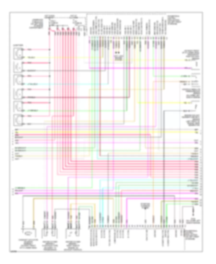
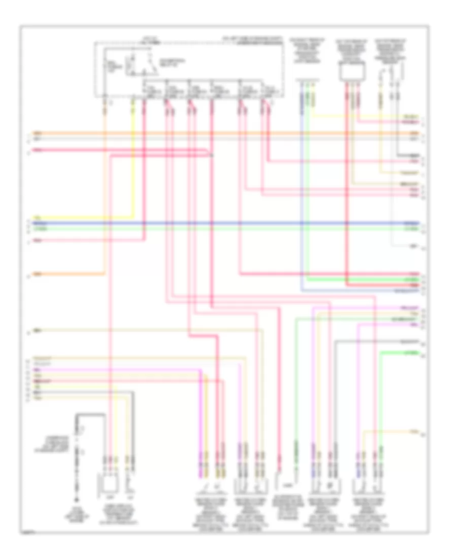
4.2L, Engine Performance Wiring Diagram (3 of 5) for Isuzu Ascender Limited 2005
List of elements for 4.2L, Engine Performance Wiring Diagram (3 of 5) for Isuzu Ascender Limited 2005:
- (on right front of cylinder head) crankshaft position (cmp) sensor
- 1-2 shift sol ctrl
- 2-3 shift sol ctrl
- 3-2 shift sol
- 5v ref
- Anti lock brakes system
- Cam pos sol hi
- Camshaft actuator solenoid assembly (on right front of cylinder head)
- Ckp sens sig
- Deliv torque sig
- Ect sens sig
- Engine coolant temperature (ect) sensor (left front of engine, near generator)
- Evap can prg ctl
- Evap can vent
- Fuel inj 1
- Fuel inj 2
- Fuel inj 3
- Fuel inj 4
- Fuel inj 5
- Fuel inj 6
- Fuel pump rly ctrl
- G108 (on lower left side of engine)
- Gfd cyc sig
- Ground powertrain control module (pcm) (on left front of engine)
- H02 hi sig b1 s2
- H02s hi sig b1 s1
- H02s lo sig b1 s2
- Heated oxygen sensor 1 (right side of engine, on exhaust manifold)
- Heated oxygen sensor 2 (in exhaust pipe, adjacent to transmission)
- Ho2s htr lo b1 s1
- Ho2s htr lo b1 s2
- Ho2s lo sig b1 s1
- Hot at all times
- Hot in run or start
- Ic 1 ctrl
- Ic 2 ctrl
- Ic 3 ctrl
- Ic 4 ctrl
- Ic 5 ctrl
- Ic 6 ctrl
- Injectors
- Low ref
- Manifold absolute pressure (map) sensor (on upper left side of engine)
- Map sens sig
- Nca
- O2 fuse 29 10a
- Oil pres sw sig
- Pc sol high ctrl
- Pc sol low ctrl
- Pcm 1 fuse 28 15a
- Pnk
- Powertrain control module (pcm) (on left front of engine)
- Req torque sig
- Starting/ charging system
- Tan
- Tcc pwm sol
- Tcc sol vlv ctrl
- Trans range sw a
- Underhood fuse block (on left side of engine compartment)
- Vss high sig
- Vss low signal
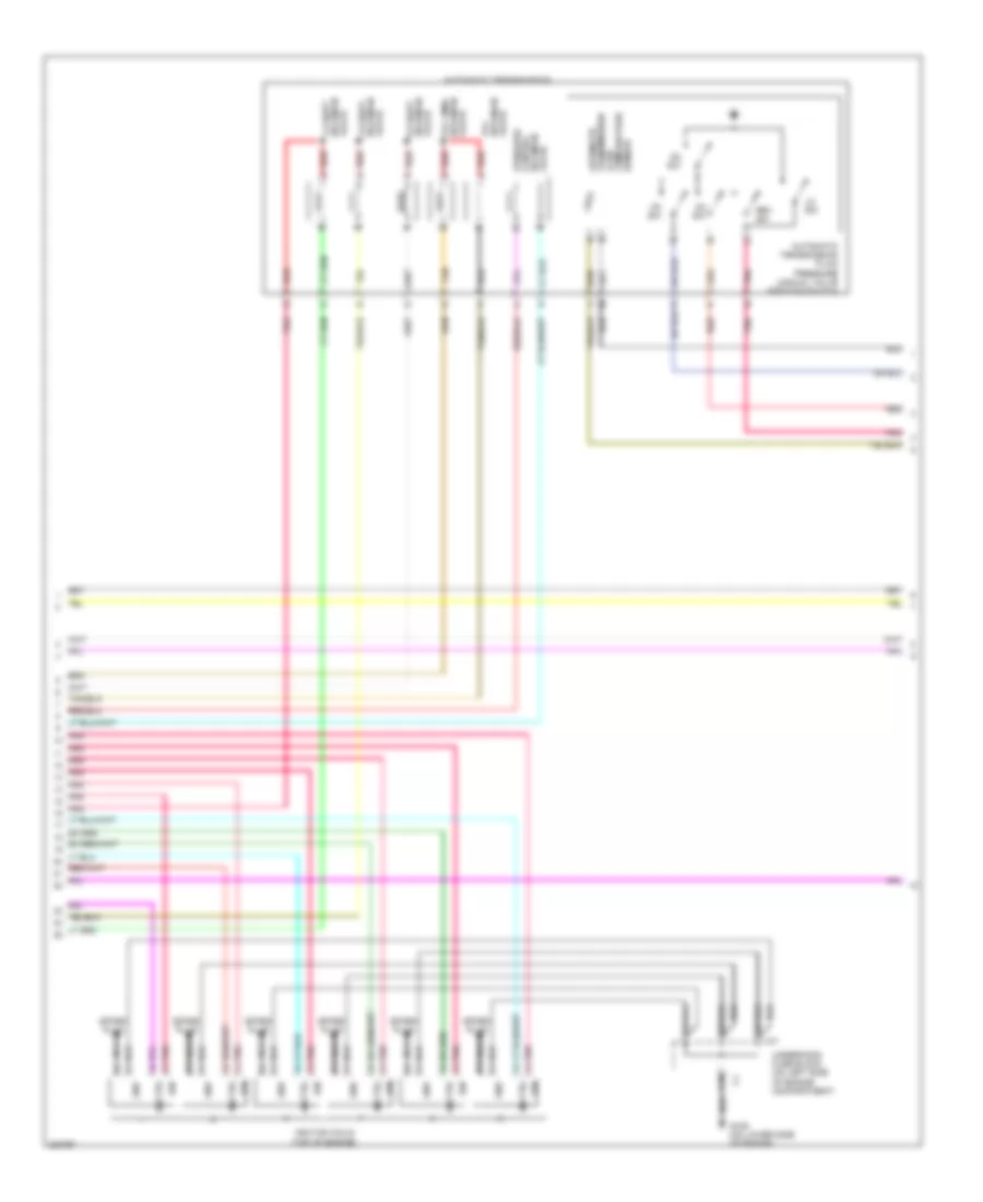
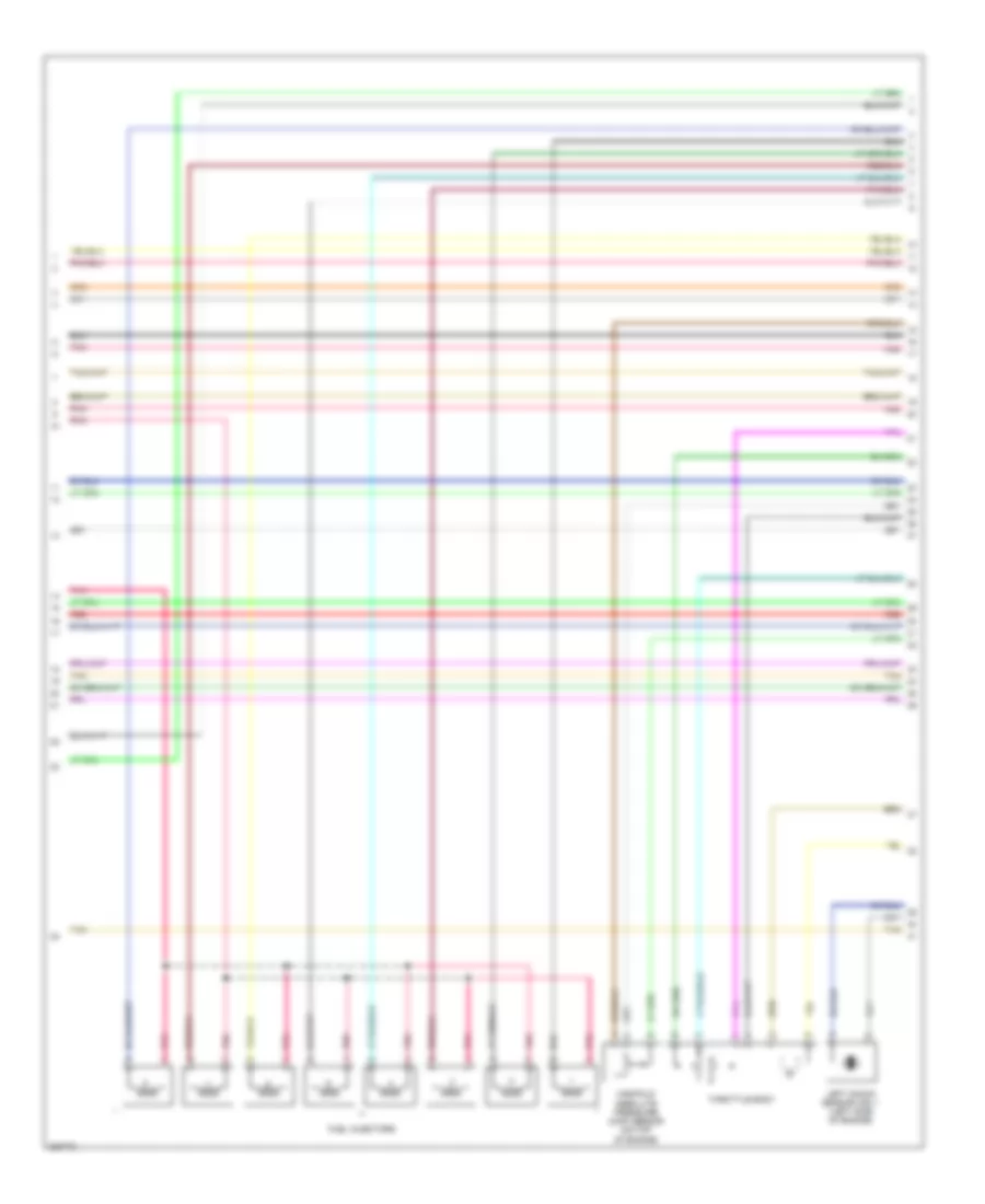
4.2L, Engine Performance Wiring Diagram (4 of 5) for Isuzu Ascender Limited 2005
List of elements for 4.2L, Engine Performance Wiring Diagram (4 of 5) for Isuzu Ascender Limited 2005:
- Automatic
- Automatic transmission
- Automatic transmission fluid pressure manual valve position switch
- C10
- Ctrl
- D10
- D2 sw
- D3 sw
- D4 sw
- E10
- F10
- G109 (on lower side of engine)
- Gnd
- Ign
- Ignition coils (top of engine)
- Lo sw
- Nca
- Pnk
- Pnk a
- Pressure control
- Red
- Rev sw
- Solenoid 1-2 shift red
- Solenoid 2-3 shift red
- Solenoid 3-2 shift red
- Solenoid tcc pmw red
- Solenoid tcc red
- Solenoid valve
- Spark plug
- Tan
- Temperature sensor
- Transmission fluid
- Underhood fuse block (on left side of engine compartment)
- Valve
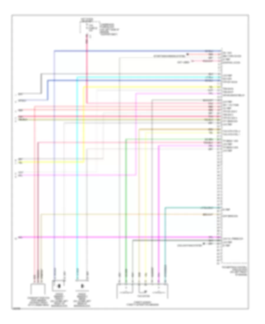
4.2L, Engine Performance Wiring Diagram (5 of 5) for Isuzu Ascender Limited 2005
List of elements for 4.2L, Engine Performance Wiring Diagram (5 of 5) for Isuzu Ascender Limited 2005:
- (not used)
- 12v ref
- 5v ref
- Air solenoid relay
- Camshaft position (cmp) sensor (on right front of cylinder head)
- Cmp sens sig
- Cooling fans system
- Damping l/d sig
- Gen turn on sig
- Hot in run or start
- Ign 1 voltage
- Knock sensor 1 (front) (on lower left front of engine block)
- Knock sensor 2 (rear) (on lower left rear of engine block)
- Ks 1 sig
- Ks 2 sig
- Low oil press sw
- Low ref
- Pnk
- Powertrain control module (pcm) (on left front of engine)
- Red
- Starting/charging system
- Tac fuse 23 10a
- Tac motor
- Tac mtr ctrl 1
- Tac mtr ctrl 2
- Tfp sw sig a
- Tfp sw sig b
- Tfp sw sig c
- Tft sens sig
- Throttle body (throttle position sensor)
- Tp sens 1 sig
- Tp sens 2 sig
- Trs sig b
- Trs sig c
- Trs sig p
- Underhood fuse block (on left side of engine compartment)
5.3L
5.3L, Engine Performance Wiring Diagram (1 of 5) for Isuzu Ascender Limited 2005
List of elements for 5.3L, Engine Performance Wiring Diagram (1 of 5) for Isuzu Ascender Limited 2005:
- (not used)
- 5 volt
- A/c ref pre sen
- A/c refrigerant pressure sensor (on bottom right side of engine)
- A12
- Anti-lock brakes system
- App sens 1
- App sens 2
- Battery
- Computer data lines system
- Cool fan clu ctrl
- Cool fan speed sig
- Cooling fans system
- Crank fuse 17 10a
- Crank volt
- Cruise control system
- Cruise on sw sig
- Ecm i fuse 10a
- Eng speed sig
- Engine control module (ecm) (on left front of engine compt)
- Engine speed
- Evap can
- Evaporative emission (evap) canister vent solenoid (rear of fuel tank)
- Exterior lights system
- Ftp sens
- Fuel lvl sens sig
- Fuel pump & sender assembly
- Fuel pump rly
- Fuel tank pressure (ftp) sensor (at top left rear of fuel tank)
- Fuel/ pmp relay
- G107 (lower left side of engine)
- G305 (on outside of left frame rail, near fuel tank)
- Hot at all times
- Hot in run or start
- Hot in start
- Ign 0 volt
- Ign 1 volt
- Ign e fuse 10a
- Instrument cluster system
- Instrument panel cluster
- Logic
- Low ref
- Malfunction indicator lamp
- Mil ctrl
- Pcm b fuse 10 20a
- Pnk
- Pnp sw
- Pwr diag
- Res/acc sw sig
- Serial data
- Serial data 2
- Set/coast sw sig
- St/lp fuse 12 25a
- Start relay
- Starting/charging system
- Stop lamp volts
- Stoplamp switch (w/o eap: on brake pedal support) (w/ eap: top of brake pedal bracket)
- Tan
- Tcc brake sw
- Tcm/ canister fuse 15 10a
- Underhood fuse block (on left side of engine compt)
- Vss
5.3L, Engine Performance Wiring Diagram (2 of 5) for Isuzu Ascender Limited 2005
List of elements for 5.3L, Engine Performance Wiring Diagram (2 of 5) for Isuzu Ascender Limited 2005:
- (on brake booster) brake booster vacuum sensor
- (w/ eap: under lfet side of i/p) (w/o eap: on accelerator bracket) accelerator pedal position (app) sensor
- 4wd lo sig
- 5 volt
- A/c comp rly
- Air conditioning system
- Anti-lock brakes system
- Brk booster
- Cooling fans system
- Cylinder shutoff solenoid 1
- Cylinder shutoff solenoid 2
- Cylinder shutoff solenoid 3
- Cylinder shutoff solenoid 4
- Del torque
- Engine control module (ecm) (on left front of engine compt)
- Front hi sig
- Ho2s hi sig
- Ho2s htr lo
- Ho2s htr sig
- Ho2s lo sig
- Hot in acc, run or start
- Iat sensor
- Ign 0 fuse 47 10a
- Low ref
- Maf sensor
- Pnk
- Rear fuse block (below left rear seat)
- Req torq
- Tan
- Transmissions system
- Valve lifter oil manifold (vlom) assembly
- Veh stop fuse 34 15a
5.3L, Engine Performance Wiring Diagram (3 of 5) for Isuzu Ascender Limited 2005
List of elements for 5.3L, Engine Performance Wiring Diagram (3 of 5) for Isuzu Ascender Limited 2005:
- (on left side of engine compt) underhood fuse block
- (on right rear of engine, near starter) crankshaft position (ckp) sensor
- (on top of of engine)
- (on top rear of engine, near transmission) camshaft position (cmp) sensor
- (on top rear of engine, near transmission) engine oil pressure (eop) sensor
- A11
- C11
- Ecm fuse 29 10a
- Eng i fuse 26 15a
- Evaporative emission (evap) canister purge solenoid
- F10
- F11 f11
- G108 (lower left side of engine)
- Heated oxygen sensor (ho2s) bank 1 sensor 1 (on left bank exhaust pipe, ahead of catalytic converter)
- Heated oxygen sensor (ho2s) bank 1 sensor 2 (on left bank exhaust pipe, behind catalytic converter)
- Heated oxygen sensor (ho2s) bank 2 sensor 1 (on right bank of exhaust pipe, ahead of catalytic converter)
- Heated oxygen sensor (ho2s) bank 2 sensor 2 (on right bank exhaust pipe, behind catalytic converter)
- Hot at all times
- Iat
- Inj a fuse 31 20a
- Inj b fuse 56 20a
- Maf
- Mass airflow (maf)/intake air temperature (iat) sensor (in air intake duct)
- Nca
- O2a fuse 55 10a
- O2b fuse 54 10a
- Pnk
- Pnk pnk
- Powertrain relay 60
- Red
- Tac fuse 23 15a
- Tan
- Underhood fuse block (on left side of engine compt)
5.3L, Engine Performance Wiring Diagram (4 of 5) for Isuzu Ascender Limited 2005
List of elements for 5.3L, Engine Performance Wiring Diagram (4 of 5) for Isuzu Ascender Limited 2005:
- Fuel injectors
- Left knock sensor (ks) 1 (left side of engine)
- Manifold absolute pressure (map) sensor (on top of engine)
- Pnk
- Red
- Tan
- Throttle body
5.3L, Engine Performance Wiring Diagram (5 of 5) for Isuzu Ascender Limited 2005
List of elements for 5.3L, Engine Performance Wiring Diagram (5 of 5) for Isuzu Ascender Limited 2005:
- (left side of engine)
- 12 volt ref
- 5 volt ref
- Ckp sensor
- Cmp sensor
- Ctrl
- Cyl shut sol 1
- Cyl shut sol 2
- Cyl shut sol 3
- Cyl shut sol 4
- Ect sens sig
- Engine control module (ecm) (on left front of engine compt)
- Engine coolant temperature (ect) sensor (left front of engine)
- Evap can sol
- Fuel inj 1 ctrl
- Fuel inj 2 ctrl
- Fuel inj 3 ctrl
- Fuel inj 4 ctrl
- Fuel inj 5 ctrl
- Fuel inj 6 ctrl
- Fuel inj 7 ctrl
- Fuel inj 8 ctrl
- G109
- Gen field
- Gnd
- Ho2s heater lo
- Ho2s hi
- Ho2s hi sig
- Ho2s htr lo
- Ho2s low
- Ho2s low sig
- Ign
- Ign ctrl 1
- Ign ctrl 2
- Ign ctrl 3
- Ign ctrl 4
- Ign ctrl 5
- Ign ctrl 6
- Ign ctrl 7
- Ign ctrl 8
- Ignition coils
- Ks 1 sens sig
- Ks 2 sensor sig
- Low ref
- Map sensor
- Nca
- Nca nca
- Oil press
- Pnk
- Red
- Ref lo
- Right knock sensor (ks) 2 (right side of engine)
- Spark plug
- Starting/ charging system
- Tac mtr ctrl 1
- Tac mtr ctrl 2
- Tan
- Tp sens 1 sig
- Tp sens 2 sig

 Čeština
 Dansk
Dansk Deutsch
 Ελληνικά
 English
 English
 Español
 Suomi
Suomi Français
 Français
 עברית
עברית Hrvatski
 Italiano
 日本語
日本語 한국어
한국어 Nederlands
 Polski
 Português
 Português
 Română
 Русский
 Slovenčina
 Slovenščina
 Svenska
 Türkçe
 中文 (中国)