SUPPLEMENTAL RESTRAINTS
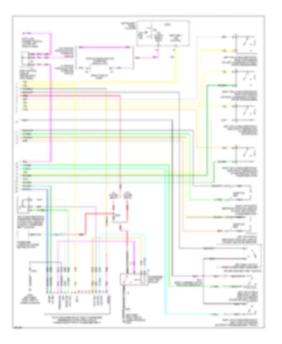
Supplemental Restraints Wiring Diagram (1 of 2) for Isuzu i-370 LS 2007
 https://portal-diagnostov.com/license.html
Automotive Electricians Portal FZCO
Automotive Electricians Portal FZCO
https://portal-diagnostov.com/license.html
https://portal-diagnostov.com/license.html
Automotive Electricians Portal FZCO
Automotive Electricians Portal FZCO
List of elements for Supplemental Restraints Wiring Diagram (1 of 2) for Isuzu i-370 LS 2007:
- Accessory switch
- Airbag fuse 10a
- Computer data lines system
- Control
- Cruise fuse 10a
- Disbl sw signal
- G302 (between front seats)
- Ground
- High control
- Hot w/ run/crank relay energized
- Hot with park lamp relay energized
- Ignition 1
- Inflatable restraint i/p module (right side of dash)
- Inflatable restraint passenger airbag on/off indicator
- Inflatable restraint sensing & diagnostic module (sdm) (beneath center console)
- Inflatable restraint steering wheel module (top of steering wheel)
- Inflatable restraint steering wheel module coil (steering wheel)
- Left front seat belt pretensioner (extended cap: in left rear door; regular/crew cab: in left "b" pillar)
- Logic
- Low control
- Low reference
- Nca
- Passenger seat belt indicator
- Pnk
- Power distribution system
- Red
- Right front seat belt pretensioner (extended cap: in right rear door; regular/crew cab: in right "b" pillar)
- Rr pk lp2 fuse 10a
- S324
- Seat belt sw
- Serial data
- Shorting bar
- Signal
- Stage 1
- Stage 2
- Tan
- Underhood fuse block (on left front side of engine compartment)
- Voltage
Supplemental Restraints Wiring Diagram (2 of 2) for Isuzu i-370 LS 2007
List of elements for Supplemental Restraints Wiring Diagram (2 of 2) for Isuzu i-370 LS 2007:
- (between front seats, under console) g302
- (right side of dash)
- A38
- A39
- A42
- Air bag ind
- Body control module (behind right kick panel)
- Data link connector (dlc) (lower left side of dash)
- Driver side seat belt buckle
- G302 (between front seats, under console)
- Grd
- Ign
- Ign 1+
- Inflatable restraint front passenger presence system (pps) module (under side of front passenger seat)
- Inflatable restraint passenger presence system (pps) sensor (in front passenger seat cushion)
- Instrument panel cluster
- Ipc class 2 serial data
- Left inflatable restraint front end sensor (on left underside of front frame crossmember)
- Left inflatable restraint roof rail module (in roof above driver door)
- Left inflatable restraint seat position sensor (on driver seat track)
- Left inflatable restraint side impact sensor (sis) (lower rear of driver door)
- Logic
- Low ref
- Nca
- Nca a
- Off ind
- On ind
- Passenger lumbar adjuster/ heater switch
- Passenger seat belt buckle
- Pnk
- Press sig
- Red
- Right inflatable restraint front end sensor (on right underside of front frame crossmember)
- Right inflatable restraint roof rail module (in roof above front passenger door)
- Right inflatable restraint seat position sensor (on front passenger seat track)
- Right inflatable restraint side impact sensor (sis) (lower rear of front passenger door)
- S311 (body harness, 24.5 cm from g302 breakout)
- S323
- S324
- Seat belt ind control
- Seat belt switch (open w/ seat belt buckled)
- Serial
- Shorting bar
- Tan
- Tension sig
- Vehicle communication interface module (vcim)
- Volt ref
- W/ power seats
- W/ vehicle communication interface module
- W/o power seats
- W/o vehicle communication interface module

 Čeština
 Dansk
Dansk Deutsch
 Ελληνικά
 English
 English
 Español
 Suomi
Suomi Français
 Français
 עברית
עברית Hrvatski
 Italiano
 日本語
日本語 한국어
한국어 Nederlands
 Polski
 Português
 Português
 Română
 Русский
 Slovenčina
 Slovenščina
 Svenska
 Türkçe
 中文 (中国)