AIR CONDITIONING
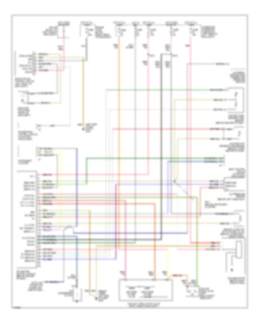
Automatic A/C Wiring Diagram for Chrysler Crossfire 2004
List of elements for Automatic A/C Wiring Diagram for Chrysler Crossfire 2004:
- (left side of eng compt) g100
- 11b
- 17a
- A/c compressor clutch
- A/c heater control module (behind center of dash)
- A/c pressure sensor (behind left headlight)
- B (+)
- Blower motor (behind right side of dash)
- Body control module in control module box)
- Clutch sig
- Coolant circulation pump (below right headlight)
- Coolant circulation valve (right side of eng compt)
- Data link connector (under left side of dash
- Defog ind
- Engine fuse block (right rear of eng compt)
- Evaporator temperature sensor (behind lower center of dash)
- Fan ctrl
- Fuse 15a
- Fuse 30a
- Fuse 50a
- Fuse 5a
- Grd
- Heater core temperature sensor (behind center of dash)
- Hot at all times
- Hot in run
- Hot in run or start
- Ign sw
- Instrument cluster
- Left-side water valve
- Lft sens sig
- Lft vlv ctrl
- Module grd
- Module out
- Mtr ctrl
- Nca
- Pnk/ red
- Pnk/red
- Powertrain control module (in control module box)
- Pump ctrl
- Radiator fan control module (left front of eng compt)
- Radiator fan motor (front of eng compt)
- Recirculated air switchover valve (behind lower right side of dash)
- Red
- Right-side water valve
- Rt sens sig
- Rt vlv ctrl
- S211 (behind instrument cluster)
- S212
- S215
- Sci transmit
- Sens grd
- Sens sig
- Serial k1
- Serial k2
- Splice block 101 (left side of eng compt)
- Sw sens
- Underhood accessory fuse block (left rear of eng compt)
- Universal garage door opener/tire pressure monitor
- Vlv ctrl
 Čeština
 Dansk
Dansk Deutsch
 Ελληνικά
 English
 English
 Español
 Suomi
Suomi Français
 Français
 עברית
עברית Hrvatski
 Italiano
 日本語
日本語 한국어
한국어 Nederlands
 Polski
 Português
 Português
 Română
 Русский
 Slovenčina
 Slovenščina
 Svenska
 Türkçe
 中文 (中国)
 Magyar