ANTI-LOCK BRAKES
Anti-lock Brakes Wiring Diagram for Chrysler Concorde LXi 2004
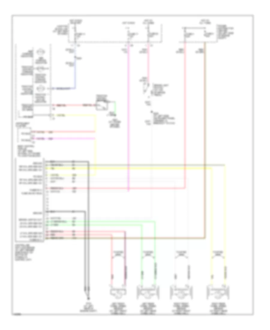
List of elements for Anti-lock Brakes Wiring Diagram for Chrysler Concorde LXi 2004:
- (at lower center of dash)
- A10
- A20
- Abs warning indicator
- Body control module (at left end of dash, attached to junction block)
- Brake lamp sw out
- Brake light switch (at top of brake pedal)
- Controller anti-lock brake (at left fender side shield, on bottom of hydraulic control unit)
- D25
- F20
- Fuse 14 10a
- Fuse 17 10a
- Fuse 20 20a
- Fuse h 30a
- Fuse ign sw (run)
- Fuse k 40a
- Fused b (+)
- G103 (at left rear of engine compt)
- G201
- Ground
- Hot at all times
- Hot in run
- Hot in run or start
- Instrument cluster
- Junction block (j/b) (at left end of dash)
- L50
- Left front wheel speed sensor (at left front wheelwell)
- Left rear wheel speed sensor (at left rear wheelwell)
- Lf whl spd sen 12v
- Lf whl spd sen sig
- Lr whl spd sen 12v
- Lr whl spd sen sig
- Pci bus
- Power distribution center (on left side of engine compt)
- Red
- Rf whl spd sen 12v
- Rf whl spd sen sig
- Right front wheel speed sensor (at right front wheelwell)
- Right rear wheel speed sensor (at right rear wheelwell)
- Rr whl spd sen 12v
- Rr whl spd sen sig
- S200
- S205 (at left side instrument panel harness, in breakout to c104)
- Traction control active indicator
- Traction control sw sens
- Traction control switch
- Traction control warning indicator
- Twisted pair
 Čeština
 Dansk
Dansk Deutsch
 Ελληνικά
 English
 English
 Español
 Suomi
Suomi Français
 Français
 עברית
עברית Hrvatski
 Italiano
 日本語
日本語 한국어
한국어 Nederlands
 Polski
 Português
 Português
 Română
 Русский
 Slovenčina
 Slovenščina
 Svenska
 Türkçe
 中文 (中国)
 Magyar