СИСТЕМА ОХЛАЖДЕНИЯ
Электросхема системы охлаждения для Pontiac Firebird Trans Am GT 1995
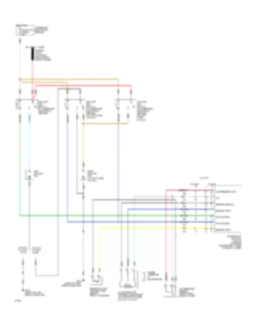
Электросхема системы охлаждения для Pontiac Firebird Trans Am GT 1995 - Список элементов:
- (v6 vin s, v8 vin p)
- +5v
- A/c evaporator temperature sensor (in evaporator core)
- A/c pressure sensor (above right shock tower)
- Compressor ctrl
- Coolant fan relay 1 (in underhood electrical center)
- Coolant fan relay 2 (in underhood electrical center) (v8 vin p w/c60, v6 vin k)
- Coolant fan relay 3 (in underhood electrical center) (v8 vin p w/c60, v6 vin k)
- Engine coolant temperature sensor (front of engine)
- Fan control
- Fans/actr fuse 6 10a
- G108 (near top left side of radiator)
- Hot at all times
- Hot in run
- Left coolant fan
- Powertrain control module (in engine compartment, rear of shock tower)
- Probe (inserted in evaporator)
- Red
- Right coolant fan (v8 vin p w/c60, v6 vin k)
- Sensor ground
- Sensor input
- Solid state
- Underhood electrical center
- V6 vin k
- V6 vin k v8 vin p w/c60
- V6 vin s
- V6 vin s v8 vin p w/c41
- V8 vin p
 Čeština
 Dansk
Dansk Deutsch
 Ελληνικά
 English
 English
 Español
 Suomi
Suomi Français
 Français
 עברית
עברית Hrvatski
 Italiano
 日本語
日本語 한국어
한국어 Nederlands
 Polski
 Português
 Português
 Română
 Русский
 Slovenčina
 Slovenščina
 Svenska
 Türkçe
 中文 (中国)
 Magyar