COOLING FAN
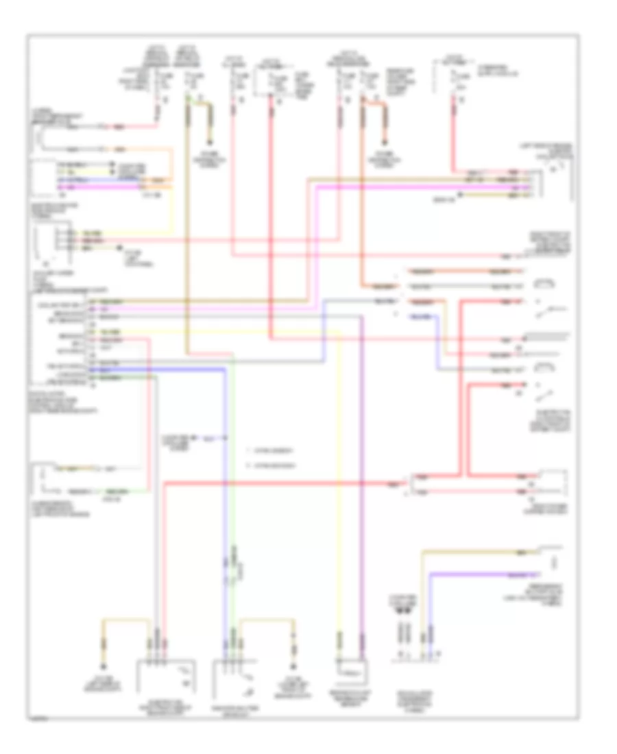
Cooling Fan Wiring Diagram for BMW 535i GT 2014
List of elements for Cooling Fan Wiring Diagram for BMW 535i GT 2014:
- (hybrid) front refrigerant shut-off valve
- (left side of engine) electric coolant pump
- (right front of battery compt) electric fan cutoff relay
- Accumulator management electronics (hybrid)
- Activation
- Auxiliary water pump (hybrid) (left front of engine compt)
- Bsd bus sig
- Characteristic map thermostat (left front of engine)
- Computer data lines system
- Coolant pmp sply
- Digital motor electronics (dme) control module (right rear engine compt)
- Ect sens gnd
- Electric fan (right front side of engine compt)
- Electric fan cutoff relay (right front of battery compt)
- Electric-machine electronics (hybrid)
- Engine coolant temperature sensor
- Fan activation
- Front power distribution box
- Fuse 100a
- Fuse 10a
- Fuse 50a
- Fuse 5a
- Fuse 60a
- Fuse 7.5a
- Fuse box (under spare tire)
- Hot at all times
- Hot w/ terminal 15n relay energized
- Hot w/ terminal 30b relay energized
- Junction box (right side of dash)
- Lin bus sig
- Nca
- Power distribution system
- Radiator shutter drive unit
- Rear fuse holder (right side of rear compt)
- Red
- Refrigerant shutoff valve (high voltage battery) (hybrid)
- Sens gnd
- Sply
- W/ fan 400/600w
- W/ fan 800/1000w
- X13 12b
- X148 1b
- X671 1b
- X705 1b
- Z10 15b (left rear of engine compt)
- Z10 2b (lower left front of engine compt)
- Z10 5b (left kick panel)
- Z6000 4b
 Čeština
 Dansk
Dansk Deutsch
 Ελληνικά
 English
 English
 Español
 Suomi
Suomi Français
 Français
 עברית
עברית Hrvatski
 Italiano
 日本語
日本語 한국어
한국어 Nederlands
 Polski
 Português
 Português
 Română
 Русский
 Slovenčina
 Slovenščina
 Svenska
 Türkçe
 中文 (中国)
 Magyar