COOLING FAN
Auxiliary Cooling Fan Wiring Diagram for BMW 735i 1991
 https://portal-diagnostov.com/license.html
Automotive Electricians Portal FZCO
Automotive Electricians Portal FZCO
https://portal-diagnostov.com/license.html
https://portal-diagnostov.com/license.html
Automotive Electricians Portal FZCO
Automotive Electricians Portal FZCO
List of elements for Auxiliary Cooling Fan Wiring Diagram for BMW 735i 1991:
- Air conditioning system
- Automatic heating & a/c control unit
- Auxiliary fan motor (center front of engine compt)
- Auxiliary relay box 1 (left side of engine compt)
- Front power distribution box (left rear of engine compt)
- Fuse f25 30a
- Fuse f29 7.5a
- G110 (left front of engine compt)
- G119 (right front of engine compt)
- High speed relay
- Hot at all times
- Hot in start or run
- Normal speed relay
- Pressure switch (front right side of engine compt)
- Temperature switch (top right of radiator)
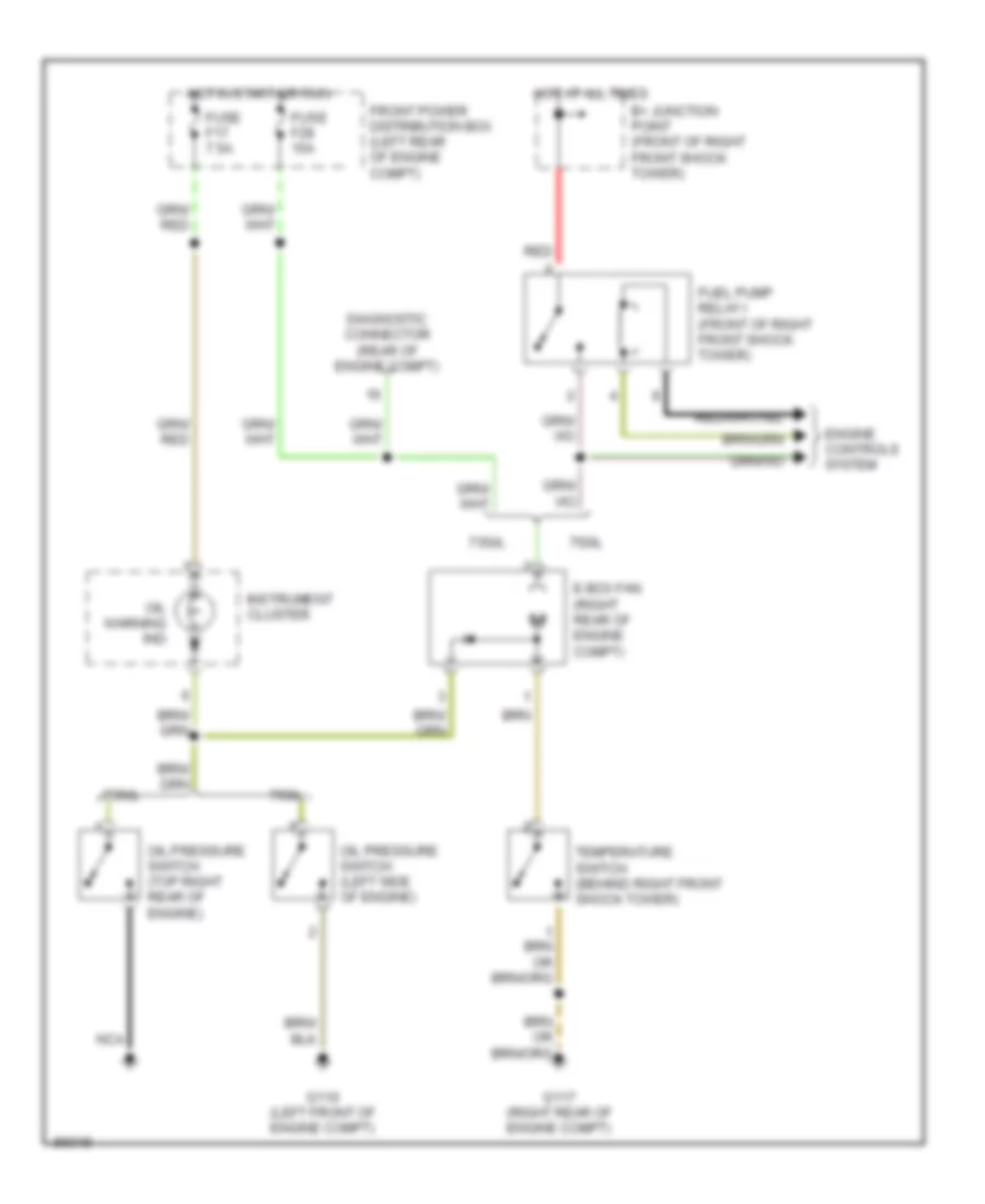
Electrical Box Fan Wiring Diagram for BMW 735i 1991
List of elements for Electrical Box Fan Wiring Diagram for BMW 735i 1991:
- 735i/l
- 750il
- B+ junction point (front of right front shock tower)
- Diagnostic connector (rear of engine compt)
- E-box fan (right rear of engine compt)
- Engine controls system
- Front power distribution box (left rear of engine compt)
- Fuel pump relay i (front of right front shock tower)
- Fuse f17 7.5a
- Fuse f28 15a
- G110 (left front of engine compt)
- G117 (right rear of engine compt)
- Hot at all times
- Hot in start or run
- Instrument cluster
- Nca
- Oil pressure switch (left side of engine)
- Oil pressure switch (top right rear of engine)
- Oil warning ind
- Red
- Temperature switch (behind right front shock tower)

 Čeština
 Dansk
Dansk Deutsch
 Ελληνικά
 English
 English
 Español
 Suomi
Suomi Français
 Français
 עברית
עברית Hrvatski
 Italiano
 日本語
日本語 한국어
한국어 Nederlands
 Polski
 Português
 Português
 Română
 Русский
 Slovenčina
 Slovenščina
 Svenska
 Türkçe
 中文 (中国)