STARTING/CHARGING
Charging Wiring Diagram for BMW 535i 1990


List of elements for Charging Wiring Diagram for BMW 535i 1990:
- Alternator
- B+ junction point (rear left side of engine compartment)
- Battery
- Charge ind
- Data link connector (rear left side of engine compartment)
- Driver seat heating relay (below driver seat)
- Front power distribution box (rear left side of engine compartment)
- Fuse f17 7.5a
- Fuse f28 15a
- G101 (right side of engine compartment)
- Hot in run and start
- Instrument cluster
- Integrated climate regulation ii control unit (ihkr ii)
- Not used (ihkr)
- Not used (m5)
- Rear defogger relay (below left side of rear seat)
- Red
- Slip control module (rear right side of engine compartment)
- Starter
- Uncoupling diode (left rear side of engine compartment) (m5)
- Unloader relay (rear left side of engine compartment)
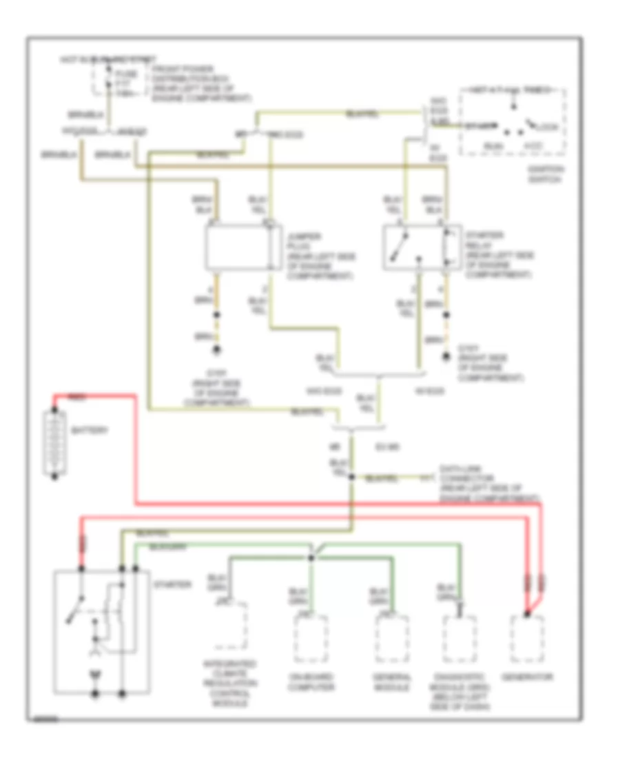
Starting Wiring Diagram for BMW 535i 1990
List of elements for Starting Wiring Diagram for BMW 535i 1990:
- Acc
- Battery
- Data link connector (rear left side of engine compartment)
- Diagnostic module (srs) (below left side of dash)
- Ex m5
- Front power distribution box (rear left side of engine compartment)
- Fuse f17 7.5a
- G101 (right side of engine compartment)
- General module
- Generator
- Hot at all times
- Hot in run and start
- Ignition switch
- Integrated climate regulation control module
- Jumper plug (rear left side of engine compartment)
- Lock
- On-board computer
- Red
- Run
- Start
- Starter
- Starter relay (rear left side of engine compartment)
- W/ egs
- W/o egs
- W/o egs & m5
 Čeština
 Dansk
Dansk Deutsch
 Ελληνικά
 English
 English
 Español
 Suomi
Suomi Français
 Français
 עברית
עברית Hrvatski
 Italiano
 日本語
日本語 한국어
한국어 Nederlands
 Polski
 Português
 Português
 Română
 Русский
 Slovenčina
 Slovenščina
 Svenska
 Türkçe
 中文 (中国)
 Magyar