ANTI-LOCK BRAKES
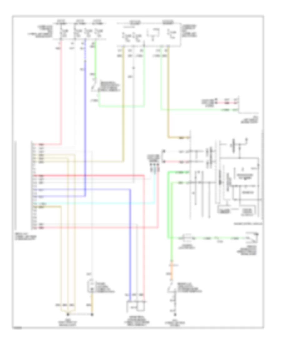
Advanced Hydraulic Booster Wiring Diagram for Acura ILX Hybrid 2013
List of elements for Advanced Hydraulic Booster Wiring Diagram for Acura ILX Hybrid 2013:
- 5v regulator
- A13
- Brake fluid level switch (on brake master cylinder reservoir)
- Brake ind
- Brake pedal position switch (top of brake pedal assembly)
- Brake pedal stroke sensor (hybrid: top of brake pedal assembly)
- Brake system ind (amber)
- C102
- C111
- C16
- Circuit
- Computer data lines system
- D17
- D31
- Driver's junction box 1
- F can transceiver
- F-can h
- F-can l
- Fail safe circuit
- Forced turning on circuit
- Fuse 1-2 40a
- Fuse 10a
- Fuse 15a
- Fuse 7.5a
- G202 (right front of engine compt)
- G401 (hybrid: left end of dash)
- Gauge control module
- Hot at all times
- Hot in on or start
- Indicator drive
- Main circuit
- Micu
- Parking brake switch (base of parking brake lever)
- Pcm (left side of engine compt)
- Power unit (eps) (hybrid: on steering rack)
- Red
- Servo unit (hybrid: left rear of engine compt)
- Under-dash fuse/relay box (under left end of dash)
- Under-hood fuse/relay box (hybrid: left rear of engine compt)
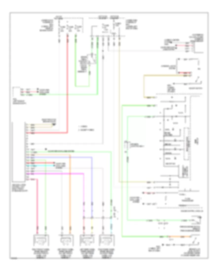
Anti-Lock Brakes Wiring Diagram for Acura ILX Hybrid 2013
List of elements for Anti-Lock Brakes Wiring Diagram for Acura ILX Hybrid 2013:
- (hybrid: center of dash) g502
- (in steering column cover) steering angle sensor
- (right front of engine compt) g202
- A13
- Abs ind
- Brake fluid level switch (on brake master cylinder reservoir)
- Brake ind (red)
- Brake pedal position switch (top of
- C102
- C103
- C111
- C120
- C123
- C16
- Circuit indicator drive
- Circuit main
- Computer data lines system
- D31
- Driver's junction box 1
- Except hybrid
- F-can h
- F-can l
- F-can transceiver
- Fuse 1-3 30a
- Fuse 1-4 30a
- Fuse 15a
- Fuse 5 7.5a
- Fuse 7.5a
- G401 (hybrid: left end of dash)
- G501 (hybrid: left end of dash)
- Gauge control module
- Hot at all times
- Hot in on or start
- Hybrid
- Interior lights system
- Left front wheel speed sensor (on left front wheel hub assembly)
- Left rear wheel speed sensor (on left rear wheel hub assembly)
- Micu
- On circuit turning compulsory
- P15
- Parking brake switch (base of parking brake lever)
- Pcm (left side of engine compt)
- Pnk
- Red
- Right front wheel speed sensor (on right front wheel hub assembly)
- Right rear wheel speed sensor (on right rear wheel hub assembly)
- Under-dash fuse/relay box (under left end of dash)
- Under-hood fuse/relay box (hybrid: left rear of engine compt)
- Vsa ind
- Vsa modulator control unit (right front of engine compt)
- Vsa off ind
- Vsa off switch

 Čeština
 Dansk
Dansk Deutsch
 Ελληνικά
 English
 English
 Español
 Suomi
Suomi Français
 Français
 עברית
עברית Hrvatski
 Italiano
 日本語
日本語 한국어
한국어 Nederlands
 Polski
 Português
 Português
 Română
 Русский
 Slovenčina
 Slovenščina
 Svenska
 Türkçe
 中文 (中国)