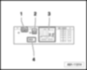
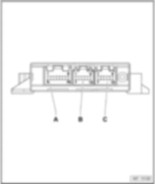
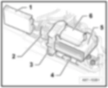
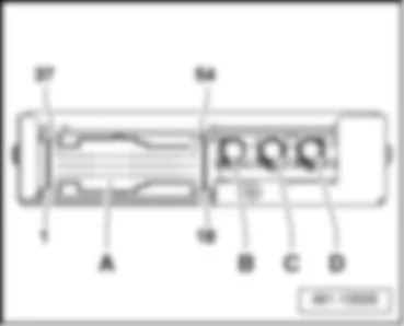
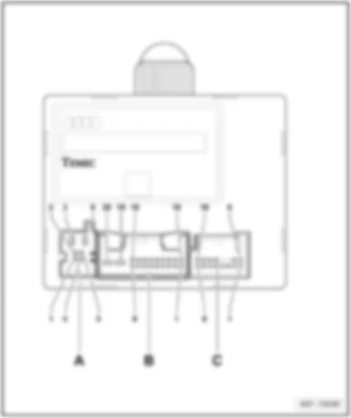
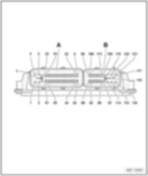
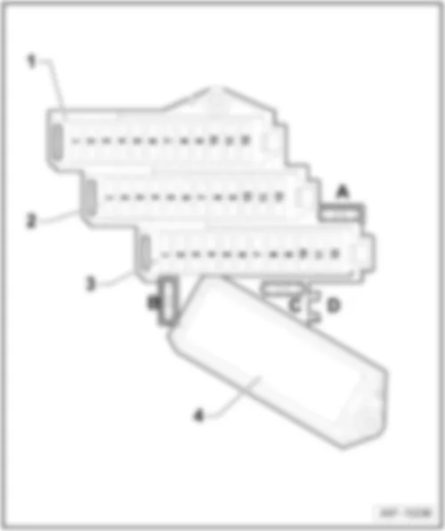
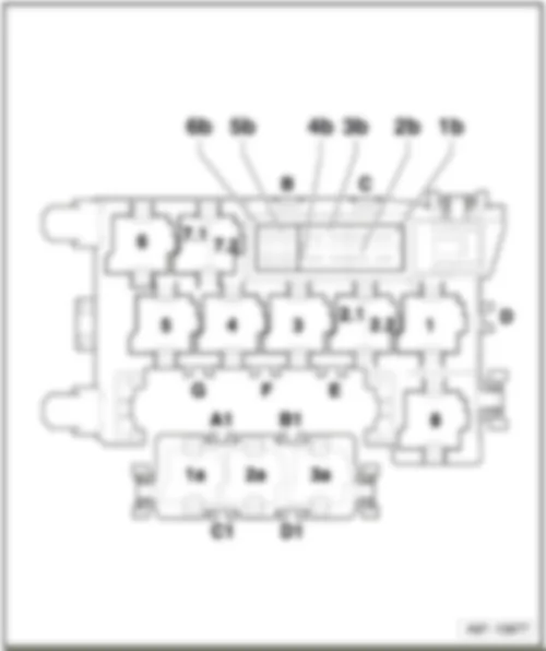
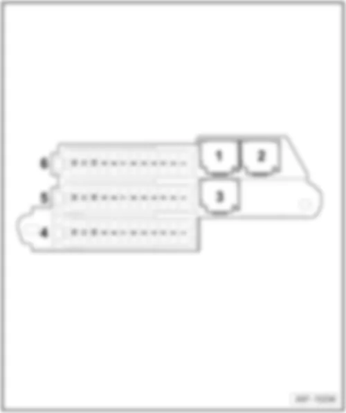
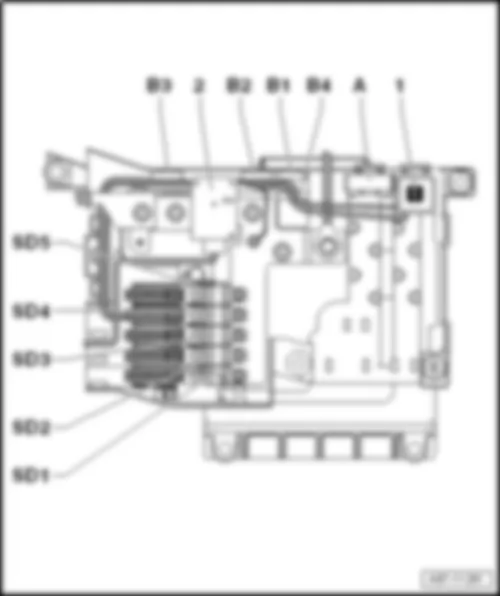
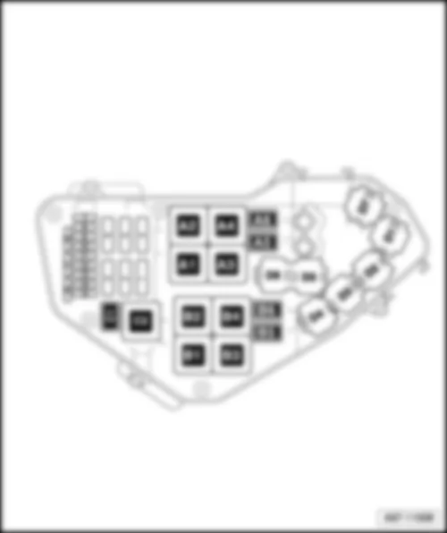
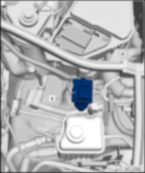
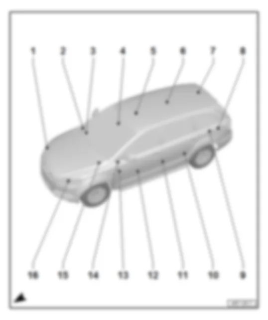
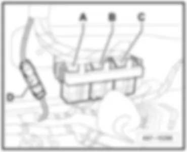
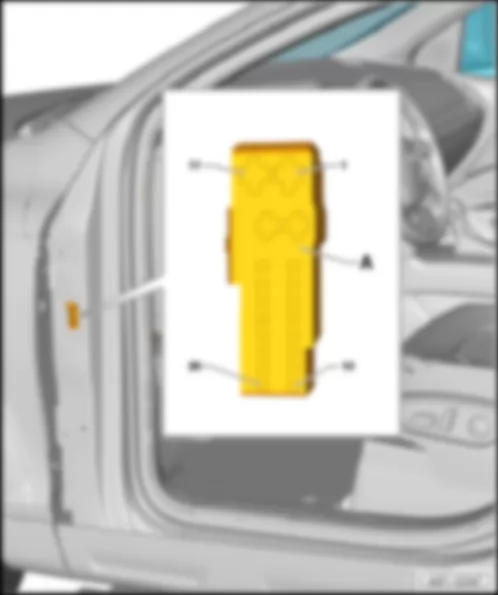
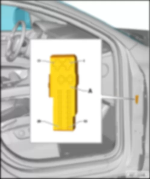
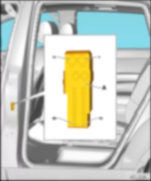
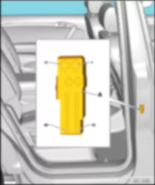
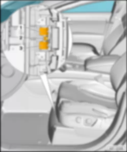
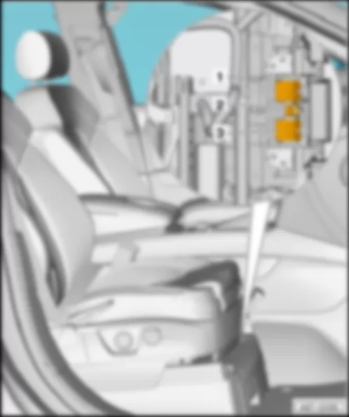
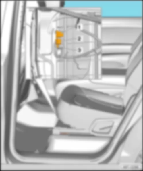
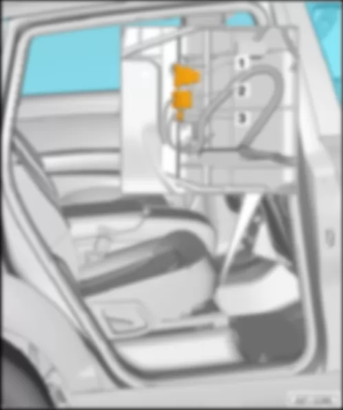
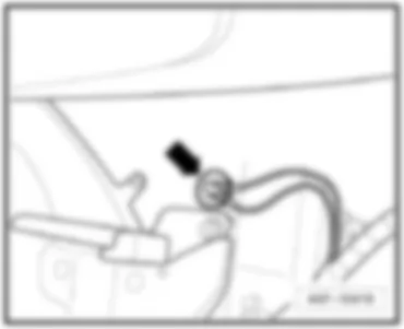
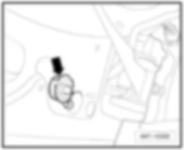
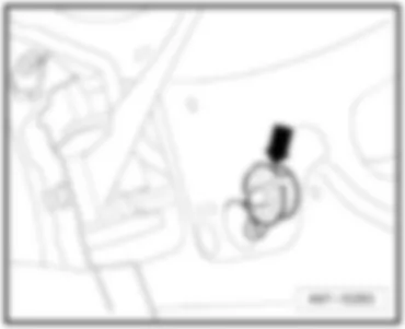
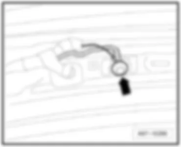
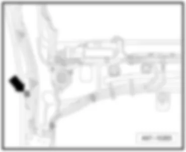
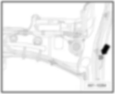
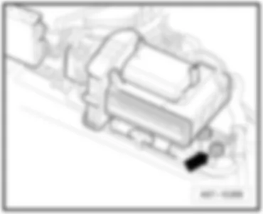
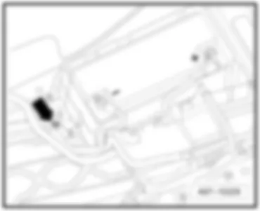
| No. | | Current Flow Diagram designation | Nominal value | | Function/component | Terminal |
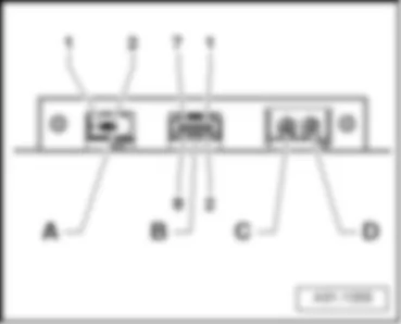
| 1 | - | Vacant | | | | |
| 2 | - | Vacant | | | | |
| 3 | - | Vacant | | | | |
| 4 | - | Fuse 4 on fuse holder B -SB4- | 5 A | - | Tyre pressure monitor control unit -J502- | 30 |
| 5 | - | Fuse 5 on fuse holder B -SB5- | 20 A | - | Auxiliary heater control unit -J364- | 30 |
| 6 | - | Fuse 6 on fuse holder B -SB6- | 10 A | - | Driver seat lumbar support adjustment switch -E176- | 30 |
| 7 | - | Fuse 7 on fuse holder B -SB7- | 35 A | - | Driver door control unit -J386-
Driver side window regulator motor -V147-
Rear left door control unit -J388-
Rear left window regulator motor -V26- | 30 |
| 8 | - | Fuse 8 on fuse holder B -SB8- | 15 A | - | Driver door control unit -J386-
Rear left door control unit -J388-1) only | 30 |
| 9 | - | Fuse 9 on fuse holder B -SB9- | 5 A | - | Energy management control unit -J644-1) only | 30 |
| 10 | - | Fuse 10 on fuse holder B -SB10- | 30 A | - | Entry and start authorisation control unit -J518-
Entryandstartauthorisationswitch -E415- | 30 |
| 11 | - | Fuse 11 on fuse holder B -SB11- | 10 A | - | Steering column electronics control unit -J527- | 30 |
| 12 | - | Fuse 12 on fuse holder B -SB12- | 5 A | - | Interior monitoring sensor -G273-
Alarm horn -H12- | 30 |
| No. | | Current Flow Diagram designation | Nominal value | | Function/component | Terminal |
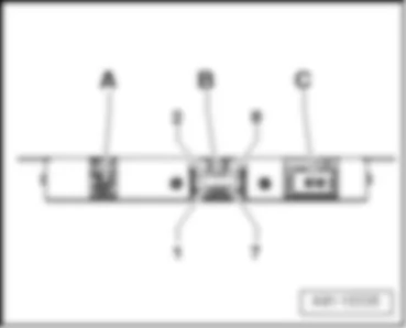
| 1 | - | Vacant | | | | |
| 2 | - | Vacant | | | | |
| 3 | - | Vacant | | | | |
| 4 | - | Fuse 4 on fuse holder B -SB4- | 30 A | - | Wiper motor control unit -J400-
Windscreen wiper motor -V- | 30 |
| 5 | - | Fuse 5 on fuse holder B -SB5- | 5 A | - | Light/rain sensor -G397- | 30 |
| 6 | - | Fuse 6 on fuse holder B -SB6- | 25 A | - | Dual tone horn relay -J4-
High tone horn -H2-
Low tone horn -H7- | 30 |
| 7 | - | Fuse 7 on fuse holder B -SB7- | 30 A | - | onboard supply control unit -J519- | 30 |
| 8 | - | Fuse 8 on fuse holder B -SB8- | 25 A | - | onboard supply control unit -J519- | 30 |
| 9 | - | Fuse 9 on fuse holder B -SB9- | 25 A | - | onboard supply control unit -J519- | 30 |
| 10 | - | Fuse 10 on fuse holder B -SB10- | 10 A | - | Control unit in dash panel insert -J285-
Data bus diagnostic interface -J533-
Display in dash panel insert -Y24- | 30 |
| 11 | - | Fuse 11 on fuse holder B -SB11- | 30 A | - | Headlight washer system relay -J39- | 30 |
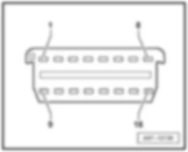
| 12 | - | Fuse 12 on fuse holder B -SB12- | 10 A | - | 16-pin connector -T16-, diagnostic connector | 30 |
| No. | | Current Flow Diagram designation | Nominal value | | Function/component | Terminal |
| 1 | - | Fuse 1 on fuse holder B -SB1- | 10 A | - | Left headlight | 15 |
| 2 | - | Fuse 2 on fuse holder B -SB2- | 5 A | - | Control unit for adaptive cruise control -J428-
Sensor heater for adaptive cruise control system -Z47- | 15 |
| 3 | - | Fuse 3 on fuse holder B -SB3- | 5 A | | Direct sight Japan
display unit -J145-
Display unit button -E506- | 15 |
| 4 | - | Fuse 4 on fuse holder B -SB4- | 10 A | - | Lane departure warning
Lane departure warning control unit -J759-
Windscreen heater for lane departure warning -Z67- | 15 |
| 5 | - | Fuse 5 on fuse holder B -SB5- | 10 A
5 A1) | - | Signal system control unit -J616-
Operating unit for special signals -E507-
Preparation for multimedia (9WM)1) | 15 |
| 6 | - | Fuse 6 on fuse holder B -SB6- | 5 A | - | Steering column electronics control unit -J527-
Entry and start authorisation control unit -J518-
Light switch -E1-
Comfort system central control unit -J393-
Trailer detector control unit -J345-
Tyre pressure monitor control unit -J502- (7K6)2) | 15 |
| 7 | - | Fuse 7 on fuse holder B -SB7- | 5 A | - | Oil level and oil temperature sender -G266- | 15 |
| 8 | - | Fuse 8 on fuse holder B -SB8- | 5 A | - | 16-pin connector -T16-, diagnostic connector | 15 |
| 9 | - | Fuse 9 on fuse holder B -SB9- | 5 A | - | Automatic anti-dazzle interior mirror -Y7- | 15 |
| 10 | - | Fuse 10 on fuse holder B -SB10- | 5 A | - | Garage door operation control unit -J530-
Garage door operating unit -E284- | 15 |
| 11 | - | Fuse 11 on fuse holder B -SB11- | 5 A | - | Data bus diagnostic interface -J533- | 15 |
| 12 | - | Fuse 12 on fuse holder B -SB12- | 5 A | - | Headlight range control regulator -E102-
Left headlight range control motor -V48-
Right headlight range control motor -V49- | 15 |
| No. | | Current Flow Diagram designation | Nominal value | | Function/component | Terminal |
| 1 | - | Vacant | | | | |
| 2 | - | Vacant | | | | |
| 3 | - | Vacant | | | | |
| 4 | - | Fuse 4 on fuse holder B -SB4- | 5 A | - | Tyre pressure monitor control unit -J502- | 30 |
| 5 | - | Fuse 5 on fuse holder B -SB5- | 20 A | - | Auxiliary heater control unit -J364- | 30 |
| 6 | - | Fuse 6 on fuse holder B -SB6- | 10 A | - | Front passenger seat lumbar support adjustment switch -E177- | 30 |
| 7 | - | Fuse 7 on fuse holder B -SB7- | 35 A | - | Front passenger door control unit -J387-
Rear right window regulator motor -V27-
Front passenger side window regulator motor -V148- | 30 |
| 8 | - | Fuse 8 on fuse holder B -SB8- | 15 A | - | Front passenger door control unit -J387-
Rear right door control unit -J389- | 30 |
| 9 | - | Fuse 9 on fuse holder B -SB9- | 5 A | - | Energy management control unit -J644-1) only | 30 |
| 10 | - | Fuse 10 on fuse holder B -SB10- | 5 A | - | Media player in position 1 -R118-
Media player in position 2 -R119-
CD changer -R41-
MiniDisc player -R153-
Video recorder and DVD player -R129-
Connection for external audio sources -R199-2) only | 30 |
| 11 | - | Fuse 11 on fuse holder B -SB11- | 10 A | - | Rear Climatronic operating and display unit -E265-
Rear fresh air blower control unit -J391- | 30 |
| 12 | - | Fuse 12 on fuse holder B -SB12- | 5 A | - | Comfort system central control unit -J393- | 30 |
| No. | | Current Flow Diagram designation | Nominal value | | Function/component | Terminal |
| 1 | - | Vacant | | | | |
| 2 | - | Vacant | | | | |
| 3 | - | Vacant | | | | |
| 4 | - | Fuse 4 on fuse holder B -SB4- | 30 A | - | Wiper motor control unit -J400-
Windscreen wiper motor -V- | 30 |
| 5 | - | Fuse 5 on fuse holder B -SB5- | 5 A | - | Light/rain sensor -G397- | 30 |
| 6 | - | Fuse 6 on fuse holder B -SB6- | 25 A | - | High tone horn -H2-
Low tone horn -H7-
Dual tone horn relay -J4- | 30 |
| 7 | | Vacant | | | | |
| 8 | - | Fuse 8 on fuse holder B -SB8- | 20 A | - | Cigarette lighter -U1- | 30 |
| 9 | - | Fuse 9 on fuse holder B -SB9- | 25 A | - | 12 V socket -U5-
12 V socket 2 -U18- | 30 |
| 10 | - | Fuse 10 on fuse holder B -SB10- | 10 A | - | Climatronic control unit -J255-
Fresh air blower control unit -J126- | 30 |
| 11 | - | Fuse 11 on fuse holder B -SB11- | 30 A | - | Headlight washer system relay -J39- | 30 |
| 12 | - | Fuse 12 on fuse holder B -SB12- | 10 A | - | 16-pin connector -T16-, diagnostic connector | 30 |
| No. | | Current Flow Diagram designation | Nominal value | | Function/component | Terminal |
| 1 | - | Fuse 1 on fuse holder B -SB1- | 10 A | - | Left headlight | 15 |
| 2 | - | Fuse 2 on fuse holder B -SB2- | 5 A | - | Control unit for adaptive cruise control -J428-
Sensor heater for adaptive cruise control system -Z47- | 15 |
| 3 | - | Fuse 3 on fuse holder B -SB3- | 5 A | - | Direct sight Japan
display unit -J145-
Display unit button -E506- | 15 |
| 4 | - | Fuse 4 on fuse holder B -SB4- | 10 A | - | Lane departure warning control unit -J759-
Windscreen heater for lane departure warning -Z67- | 15 |
| 5 | - | Fuse 5 on fuse holder B -SB5- | 5 A | - | Preparation for multimedia (9WM)1) | 15 |
| 6 | - | Fuse 6 on fuse holder B -SB6- | 5 A | - | Heated bench seat cushion for rear left seat -Z10-
Heated backrest for rear left seat -Z11-
Heated bench seat cushion for rear right seat -Z12-
Heated backrest for rear right seat -Z13- | 15 |
| 7 | - | Fuse 7 on fuse holder B -SB7- | 5 A | | Oil level and oil temperature sender -G266- | 15 |
| 8 | - | Fuse 8 on fuse holder B -SB8- | 5 A | - | 16-pin connector -T16-, diagnostic connector | 15 |
| 9 | - | Fuse 9 on fuse holder B -SB9- | 5 A | - | Automatic anti-dazzle interior mirror -Y7- | 15 |
| 10 | - | Fuse 10 on fuse holder B -SB10- | 5 A | - | Garage door operation control unit -J530-
Garage door operating unit -E284- | 15 |
| 11 | - | Fuse 11 on fuse holder B -SB11- | 5 A | - | Airbag control unit -J234- | 15 |
| 12 | - | Fuse 12 on fuse holder B -SB12- | 5 A | - | Air quality sensor -G238-
Rear Climatronic operating and display unit -E265-
Climatronic control unit -J255- | 15 |
| No. | | Current Flow Diagram designation | Nominal value | | Function/component | Terminal |
| 1 | - | Fuse 1 on fuse holder B -SB1- | 5 A | - | Voltage stabiliser -J532-1) only | 50 |
| 2 | - | Fuse 2 on fuse holder B -SB2- | 5 A | - | Relay for automatic anti-dazzle interior mirror -J910-1) only | 30 |
| 3 | - | Fuse 3 on fuse holder B -SB3- | 7.5 A | - | Control unit for information electronics 1 -J794-1) only | 30 |
| 4 | - | Fuse 4 on fuse holder B -SB4- | 5 A | - | Tyre pressure monitor control unit -J502-2) only | 30 |
| 5 | - | Fuse 5 on fuse holder B -SB5- | 20 A | - | Auxiliary heater control unit -J364- | 30 |
| 6 | - | Fuse 6 on fuse holder B -SB6- | 10 A | - | Driver seat lumbar support adjustment switch -E176- | 30 |
| 7 | - | Fuse 7 on fuse holder B -SB7- | 35 A | - | Driver door control unit -J386-
Driver side window regulator motor -V147-
Rear left door control unit -J388-
Rear left window regulator motor -V26- | 30 |
| 8 | - | Fuse 8 on fuse holder B -SB8- | 15 A | - | Driver door control unit -J386- | 30 |
| 9 | - | Fuse 9 on fuse holder B -SB9- | 5 A | - | Tyre pressure monitor control unit -J502-1) only | 30 |
| 10 | - | Fuse 10 on fuse holder B -SB10- | 30 A | - | Entry and start authorisation control unit -J518-
Entryandstartauthorisationswitch -E415- | 30 |
| 11 | - | Fuse 11 on fuse holder B -SB11- | 10 A | - | Steering column electronics control unit -J527- | 30 |
| 12 | - | Fuse 12 on fuse holder B -SB12- | 5 A | - | Interior monitoring sensor -G273-
Alarm horn -H12- | 30 |
| No. | | Current Flow Diagram designation | Nominal value | | Function/component | Terminal |
| 1 | - | Vacant | | | | |
| 2 | - | Vacant | | | | |
| 3 | - | Fuse 3 on fuse holder B -SB3- | 15 A | - | Front left seat ventilation control unit -J800- | 30 |
| 4 | - | Fuse 4 on fuse holder B -SB4- | 30 A | - | Wiper motor control unit -J400-
Windscreen wiper motor -V- | 30 |
| 5 | - | Fuse 5 on fuse holder B -SB5- | 5 A | - | Light/rain sensor -G397- | 30 |
| 6 | - | Fuse 6 on fuse holder B -SB6- | 25 A | - | Dual tone horn relay -J4-
High tone horn -H2-
Low tone horn -H7- | 30 |
| 7 | - | Fuse 7 on fuse holder B -SB7- | 30 A | - | onboard supply control unit -J519- | 30 |
| 8 | - | Fuse 8 on fuse holder B -SB8- | 25 A | - | onboard supply control unit -J519- | 30 |
| 9 | - | Fuse 9 on fuse holder B -SB9- | 25 A | - | onboard supply control unit -J519- | 30 |
| 10 | - | Fuse 10 on fuse holder B -SB10- | 10 A | - | Control unit in dash panel insert -J285-1)
Diagnostic interface for data bus -J533-
Display in dash panel insert -Y24-1) only | 30 |
| 11 | - | Fuse 11 on fuse holder B -SB11- | 30 A | - | Headlight washer system relay -J39- | 30 |
| 12 | - | Fuse 12 on fuse holder B -SB12- | 10 A | - | 16-pin connector -T16-, diagnostic connector | 30 |
| No. | | Current Flow Diagram designation | Nominal value | | Function/component | Terminal |
| 1 | - | Fuse 1 on fuse holder B -SB1- | 10 A | - | Left headlight | 15 |
| 2 | - | Fuse 2 on fuse holder B -SB2- | 5 A | - | Control unit for adaptive cruise control -J428-
Sensor heater for adaptive cruise control system -Z47- | 15 |
| 3 | - | Fuse 3 on fuse holder B -SB3- | 5 A | | Direct sight Japan
display unit -J145-
Display unit button -E506-
Coolant shut-off valve relay -J541-1)
Heater coolant shut-off valve -N279-1) only | 15 |
| 4 | - | Fuse 4 on fuse holder B -SB4- | 10 A | - | Lane departure warning
Lane departure warning control unit -J759-
Windscreen heater for lane departure warning -Z67- | 15 |
| 5 | - | Fuse 5 on fuse holder B -SB5- | 5 A | - | Preparation for multimedia (9WM) | 15 |
| 6 | - | Fuse 6 on fuse holder B -SB6- | 5 A | - | Steering column electronics control unit -J527-
Entry and start authorisation control unit -J518-
Light switch -E1-
Comfort system central control unit -J393-
Trailer detector control unit -J345-
Tyre pressure monitor control unit -J502- (7K6) | 15 |
| 7 | - | Fuse 7 on fuse holder B -SB7- | 5 A | - | Oil level and oil temperature sender -G266- | 15 |
| 8 | - | Fuse 8 on fuse holder B -SB8- | 5 A | - | 16-pin connector -T16- (diagnostic connector) | 15 |
| 9 | - | Fuse 9 on fuse holder B -SB9- | 5 A | - | Automatic anti-dazzle interior mirror -Y7- | 15 |
| 10 | - | Fuse 10 on fuse holder B -SB10- | 5 A | - | Garage door operation control unit -J530-
Garage door operating unit -E284- | 15 |
| 11 | - | Fuse 11 on fuse holder B -SB11- | 5 A | - | Data bus diagnostic interface -J533- | 15 |
| 12 | - | Fuse 12 on fuse holder B -SB12- | 5 A | - | Headlight range control regulator -E102-
Left headlight range control motor -V48-
Right headlight range control motor -V49- | 15 |
| No. | | Current Flow Diagram designation | Nominal value | | Function/component | Terminal |
| 1 | - | Fuse 1 on fuse holder B -SB1- | 5 A | - | Voltage stabiliser -J532-1) only | 30 |
| 2 | - | Fuse 2 on fuse holder B -SB2- | 5 A | - | Relay for automatic anti-dazzle interior mirror -J910-1) only | 30 |
| 3 | - | Fuse 3 on fuse holder B -SB3- | 7.5 A | - | Control unit for information electronics 1 -J794-1) only | 30 |
| 4 | - | Fuse 4 on fuse holder B -SB4- | 5 A | - | Tyre pressure monitor control unit -J502-2) only | 30 |
| 5 | - | Fuse 5 on fuse holder B -SB5- | 20 A | - | Auxiliary heater control unit -J364- | 30 |
| 6 | - | Fuse 6 on fuse holder B -SB6- | 10 A | - | Front passenger seat lumbar support adjustment switch -E177- | 30 |
| 7 | - | Fuse 7 on fuse holder B -SB7- | 35 A | - | Front passenger door control unit -J387-
Rear right window regulator motor -V27-
Front passenger side window regulator motor -V148- | 30 |
| 8 | - | Fuse 8 on fuse holder B -SB8- | 15 A | - | Front passenger door control unit -J387-
Rear right door control unit -J389- | 30 |
| 9 | - | Fuse 9 on fuse holder B -SB9- | 5 A | - | Tyre pressure monitor control unit -J502-1) only | 30 |
| 10 | - | Fuse 10 on fuse holder B -SB10- | 5 A | - | CD changer -R41-2)
DVD player -R7-2) only | 30 |
| 11 | - | Fuse 11 on fuse holder B -SB11- | 10 A | - | Rear Climatronic operating and display unit -E265-
Rear fresh air blower control unit -J391- | 30 |
| 12 | - | Fuse 12 on fuse holder B -SB12- | 5 A | - | Comfort system central control unit -J393- | 30 |
| No. | | Current Flow Diagram designation | Nominal value | | Function/component | Terminal |
| 1 | - | Vacant | | | | |
| 2 | - | Vacant | | | | |
| 3 | - | Fuse 3 on fuse holder B -SB3- | 15 A | - | Front left seat ventilation control unit -J800- | 30 |
| 4 | - | Fuse 4 on fuse holder B -SB4- | 30 A | - | Wiper motor control unit -J400-
Windscreen wiper motor -V- | 30 |
| 5 | - | Fuse 5 on fuse holder B -SB5- | 5 A | - | Light/rain sensor -G397- | 30 |
| 6 | - | Fuse 6 on fuse holder B -SB6- | 25 A | - | High tone horn -H2-
Low tone horn -H7-
Dual tone horn relay -J4- | 30 |
| 7 | - | Fuse 7 on fuse holder B -SB7- | 25 A | - | 12 V socket 3 -U19-1)
12 V socket 4 -U20-1) only | 30 |
| 8 | - | Fuse 8 on fuse holder B -SB8- | 20 A | - | Cigarette lighter -U1- | 30 |
| 9 | - | Fuse 9 on fuse holder B -SB9- | 25 A | - | 12 V socket -U5-
12 V socket 2 -U18- | 30 |
| 10 | - | Fuse 10 on fuse holder B -SB10- | 10 A | - | Climatronic control unit -J255-
Fresh air blower control unit -J126- | 30 |
| 11 | - | Fuse 11 on fuse holder B -SB11- | 30 A | - | Headlight washer system relay -J39- | 30 |
| 12 | - | Fuse 12 on fuse holder B -SB12- | 10 A | - | 16-pin connector -T16-, diagnostic connector | 30 |
| No. | | Current Flow Diagram designation | Nominal value | | Function/component | Terminal |
| 1 | - | Fuse 1 on fuse holder B -SB1- | 10 A | - | Left headlight | 15 |
| 2 | - | Fuse 2 on fuse holder B -SB2- | 5 A | - | Control unit for adaptive cruise control -J428-
Sensor heater for adaptive cruise control system -Z47- | 15 |
| 3 | - | Fuse 3 on fuse holder B -SB3- | 5 A | - | Direct sight Japan
display unit -J145-
Display unit button -E506-
Coolant shut-off valve relay -J541-1)
Heater coolant shut-off valve -N279-1) only | 15 |
| 4 | - | Fuse 4 on fuse holder B -SB4- | 10 A | - | Lane departure warning control unit -J759-
Windscreen heater for lane departure warning -Z67- | 15 |
| 5 | - | Fuse 5 on fuse holder B -SB5- | 5 A | - | Preparation for multimedia (9WM) | 15 |
| 6 | - | Fuse 6 on fuse holder B -SB6- | 5 A | - | Heated bench seat cushion for rear left seat -Z10-
Heated backrest for rear left seat -Z11-
Heated bench seat cushion for rear right seat -Z12-
Heated backrest for rear right seat -Z13- | 15 |
| 7 | - | Fuse 7 on fuse holder B -SB7- | 5 A | | Oil level and oil temperature sender -G266- | 15 |
| 8 | - | Fuse 8 on fuse holder B -SB8- | 5 A | - | 16-pin connector -T16-, diagnostic connector | 15 |
| 9 | - | Fuse 9 on fuse holder B -SB9- | 5 A | - | Automatic anti-dazzle interior mirror -Y7- | 15 |
| 10 | - | Fuse 10 on fuse holder B -SB10- | 5 A | - | Garage door operation control unit -J530-
Garage door operating unit -E284- | 15 |
| 11 | - | Fuse 11 on fuse holder B -SB11- | 5 A | - | Airbag control unit -J234- | 15 |
| 12 | - | Fuse 12 on fuse holder B -SB12- | 5 A | - | Air quality sensor -G238-
Rear Climatronic operating and display unit -E265-
Climatronic control unit -J255- | 15 |
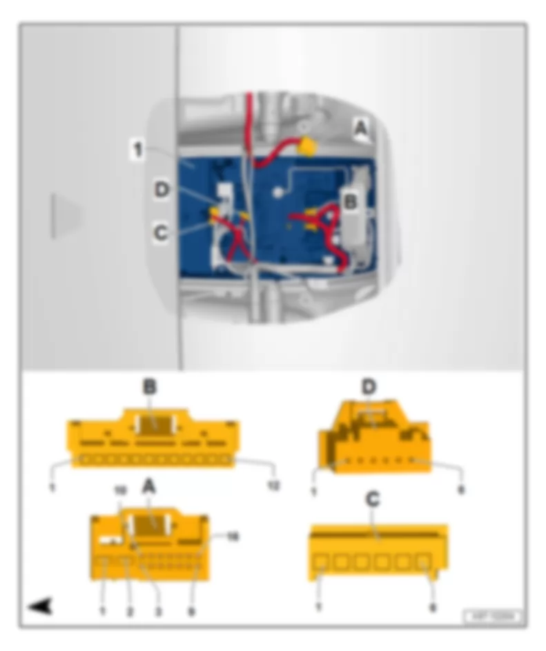
| No. | | Current Flow Diagram designation | Nominal value | | Function/component | Terminal |
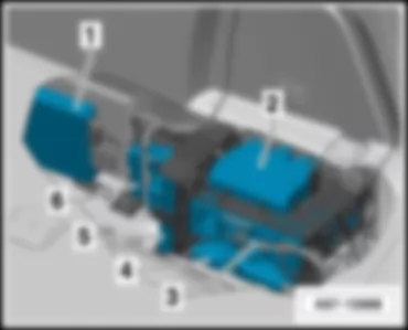
| B | - | Vacant | | | | |
| C | - | Trailer towing attachment thermal fuse -S87- | 30 A | - | Trailer detector control unit -J345- (only USA)
Brake booster (only USA) | 30 |
| D | - | Driver seat adjustment thermal fuse 1 -S44- | 30 A | - | Control unit for seat adjustment and steering column adjustment with memory function -J136-
Control unit for front passenger seat adjustment with memory function -J521- | 30 |
| E | - | Vacant | | | | |
| F | - | Vacant | | | | |
| G | - | Vacant | | | | |
| 1b | - | Fresh air blower fuse 1 -S97- | 40 A | - | Fresh air blower -V2- | 30 |
| 2b | - | ABS control unit fuse 1 -S123- | 40 A | - | ABS control unit -J104- | 30 |
| 3b | - | Fresh air blower fuse 2 -S98- | 40 A | - | Rear fresh air blower -V80- | 30 |
| 4b | - | Heated rear window fuse -S41- | 40 A | - | Heated rear window -Z1- | 30 |
| 5b | - | Rear window wiper single fuse -S30- | 15 A | - | Rear window wiper motor -V12-1) only | 75 |
| 6b | - | Fuse -S51- | 5 A | - | Left washer jet heater element -Z20-1)
Right washer jet heater element -Z21-1) only | 75 |
| A1 | - | Vacant | | | | |
| B1 | - | Vacant | | | | |
| C1 | - | Vacant | | | | |
| D1 | - | Vacant | | | | |
| No. | | Current Flow Diagram designation | Nominal value | | Function/component | Terminal |
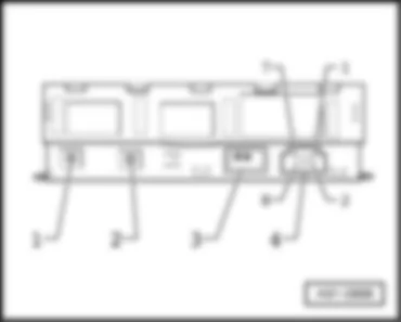
| 1 | - | Fuses in relay plate fuse holder -S1- | 40 A/ 60 A | - | Radiator fan -V7- | 30 |
| 2 | - | Fuses in relay plate fuse holder -S2- | 50 A | - | Secondary air pump motor -V101- | 30 |
| 3 | - | Vacant | | | | |
| 4 | - | Fuses in relay plate fuse holder -S4- | 40 A/ 60 A | - | Radiator fan 2 -V177- | 30 |
| 5 | - | Fuses in relay plate fuse holder -S5- | 50 A | - | Motor for secondary air pump 2 -V189- | 30 |
| 6 | - | Vacant | | | | |
| 7 | - | Fuses in relay plate fuse holder -S7- | 30 A
20 A4) | - | Ignition coils | 87 |
| 8 | - | Fuses in relay plate fuse holder -S8- | 5 A | - | Radiator fan control unit -J293-
Radiator fan control unit 2 -J671- | 87 |
| 9 | - | Fuses in relay plate fuse holder -S9- | 15 A | - | Engine control unit -J623-
Injectors | 87 |
| 10 | - | Fuses in relay plate fuse holder -S10- | 10 A | - | High-pressure sender -G65-1) 2) 3)
Coolant circulation pump -V50-1)
Map-controlled engine cooling system thermostat -F265-1)
Continued coolant circulation relay -J151-1)
Camshaft control valve 1 -N205-1) 2) 3)
Camshaft control valve 2 -N208-1) 3)
Intake manifold flap valve -N316-1)
Exhaust camshaft control valve 1 -N318-1) 2)
Exhaust camshaft control valve 2 -N319-1)
Intake manifold flap valve 2 -N403-1)
Charge air cooling pump -V188-3) only | 87 |
| 11 | - | Fuses in relay plate fuse holder -S11- | 5 A | - | Engine control unit -J623-
Air mass meter -G70-2) only | 87 |
| 12 | - | Fuses in relay plate fuse holder -S12- | 5 A | - | Crankcase breather heater element -N79- | 87 |
| 13 | - | Fuses in relay plate fuse holder -S13- | 15 A | - | Air mass meter -G70-1)
Air mass meter 2 -G246-1)
Activated charcoal filter solenoid valve 1 -N80-1) 2)
Secondary air inlet valve -N112-1) 3)
Fuel metering valve -N290-1) 2)
Intake manifold flap valve -N316-2) 3)
Secondary air inlet valve 2 -N320-1) 3)
Fuel metering valve 2 -N402-1)
Oil pressure control valve -N428-3)
Continued coolant circulation pump -V51-3)
Fuel system diagnostic pump -V144-1) 2) 3)
Crankcase breather system shut-off valve -N548-3) only | 87 |
| 14 | - | Fuses in relay plate fuse holder -S14- | 15 A | - | Lambda probe -G39-
Lambda probe 2 -G108- | 87 |
| 15 | - | Fuses in relay plate fuse holder -S15- | 15 A | - | Lambda probe downstream of catalytic converter -G130-
Lambda probe 2 downstream of catalytic converter -G131- | 87 |
| 16 | - | Fuses in relay plate fuse holder -S16- | 30 A | - | Fuel pump control unit -J538- | 87 |
| 17 | - | Fuses in relay plate fuse holder -S17- | 5 A | - | Engine control unit -J623- | 87 |
| 18 | - | Fuses in relay plate fuse holder -S18- | 15 A | - | Vacuum pump for brakes -V192-1) 2) | 87 |
| No. | | Current Flow Diagram designation | Nominal value | | Function/component | Terminal |
| 1 | - | Fuses in relay plate fuse holder -S1- | 60 A | - | Radiator fan control unit -J293-
Radiator fan -V7- | 30 |
| 2 | - | Fuses in relay plate fuse holder -S2- | 80 A | - | Automatic glow period control unit -J179- | 30 |
| 3 | - | Fuses in relay plate fuse holder -S3- | 40 A | - | Heater element for auxiliary air heater -Z35- (400 W)4) 11) 13) | 30 |
| 4 | - | Fuses in relay plate fuse holder -S4- | 40 A1)
60 A2) | - | Radiator fan control unit 2 -J671-
Radiator fan 2 -V177- | 30 |
| 5 | - | Fuses in relay plate fuse holder -S5- | 80 A
60 A13) 15) | - | Glow period control unit 2 -J703-3) 5) 6) 10)
Relay for 3rd heat setting -J959-13) 15) | 30 |
| 6 | - | Fuses in relay plate fuse holder -S6- | 80 A
60 A 13) 15) | - | Heater element for auxiliary air heater -Z35- (2 x 400 W)4) 11) | 30 |
| 7 | - | Fuses in relay plate fuse holder -S7- | 15 A | - | Map-controlled engine cooling system thermostat -F265-9) 13)
Automatic glow period control unit -J179-
Throttle valve module -J338-4) 5) 8) 11)
Low heat output relay -J359-4) 11) 13)
High heat output relay -J360-4) 11) 13)
Turbocharger 1 control unit -J724-7)
Turbocharger 2 control unit -J725-6)
Control unit for charge air cooler bypass -J865-4) 11)
Exhaust gas recirculation valve -N18-7)
Exhaust gas recirculation cooler changeover valve -N345-
Exhaust gas recirculation cooler changeover valve 2 -N381-4) 11)
Electro-hydraulic engine mounting solenoid valve -N398-9) 13)
Oil pressure control valve -N428-3) 4) 9) 10) 11) 13)
Cylinder head coolant valve -N489-9) 10) 13)
Intake manifold flap motor -V157-6) 7)
Motor for intake manifold flap 2 -V275-7) only | 87 |
| 8 | - | Fuses in relay plate fuse holder -S8- | 5 A | - | Radiator fan control unit -J293-
Radiator fan control unit 2 -J671- | 87 |
| 9 | - | Fuses in relay plate fuse holder -S9- | 15 A | - | Engine control unit -J623-
Engine control unit 2 -J624-3) 5) 6) 10) | 87 |
| 10 | - | Fuses in relay plate fuse holder -S10- | 10 A | - | Fuel pressure regulating valve -N276-
Fuel metering valve -N290-
Fuel metering valve 2 -N402-5)
Fuel pressure regulating valve 2 -N484-5) only | 87 |
| 11 | - | Fuses in relay plate fuse holder -S11- | 15 A
10 A9) 11) | - | Lambda probe -G39-
Lambda probe 2 -G108-3) 5) 6) 10)
Lambda probe heater -Z19-
Lambda probe 2 heater -Z28-3) 5) 6) 10) | 87 |
| 12 | - | Fuses in relay plate fuse holder -S12- | 10 A
5 A4) 14) | - | Fuel cooling pump relay -J445-3) 5) 6)
NOx sender control unit -J583-4) 13)
NOx sender 2 control unit -J881-4) 11) 13)
Fuel cooling pump -V166-3) 6)
Exhaust gas recirculation cooler pump -V400-3) 5) 10)
vacant 7) 8) 9)
Particle sensor -G784-13) only | 87 |
| 13 | - | Fuses in relay plate fuse holder -S13- | 10 A
15 A4) 5) | - | High-pressure sender -G65-
Continued coolant circulation relay -J151-
Fuel cooling pump relay -J445-4) 7) 8)
Glow period control unit 2 -J703-3) 5) 6) 10)
Exhaust gas recirculation cooler change-over valve 2 -N381-5)
Coolant circulation pump -V50-
Continued coolant circulation pump -V51-4) 8) 10) 11)
Fuel cooling pump -V166-4) 7) 8)
Motor for intake manifold flap 2 -V275-6)
Exhaust gas recirculation cooler pump -V400-4) 8) | 87 |
| 14 | - | Fuses in relay plate fuse holder -S14- | 5 A | - | Air mass meter -G70-
Air mass meter 2 -G246-3) 5) 6) 10) | 15 |
| 15 | - | Fuses in relay plate fuse holder -S15- | 5 A | - | Engine control unit -J623-
Engine control unit 2 -J624-3) 5) 6) 10) | 15 |
| 16 | - | Fuses in relay plate fuse holder -S16- | 20 A
25 A | - | Fuel system pressurisation pump -G6-
Fuel pump control unit -J538-9) 10) 13) | 87 |
| 17 | - | Fuses in relay plate fuse holder -S17- | 20 A | - | Fuel pump -G23-5) 6) 7) 8) | 87 |
| | | | 10 A | - | Pressure sender for reducing agent metering system -G686-4)
Reducing agent pump -V437-4)
Heater for reducing-agent pump -Z103-4) only | 87 |
| | | | 5 A | - | Engine control unit -J623-9) 10) 11) 13)
Engine control unit 2 -J624-10) only | 87 |
| 18 | - | Fuses in relay plate fuse holder -S18- | 7.5 A | - | Crankcase breather heater element -N79-3) 5) 6) 10)
Crankcase breather heater element 2 -N483-3) 5) 10) | 15 |
| | | | 20 A | - | Relay for supplementary fuel pump -J832-4) 8)
Supplementary fuel pump -V393-4) 8) | 15 |
| | | | 10 A
5 A12) | - | Pressure sender for reducing agent metering system -G686-11) 13)
Reducing agent pump -V437-11) 13)
Heater for reducing-agent pump -Z103-11) 13) | 15 |
 Deutsch
 English
 English
 Español
 Français
 Nederlands
 Русский

