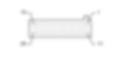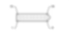

WIRING DIAGRAM - PREPARATION FOR CELLULAR TELEPHONE - Alfa Romeo 159 1.8 Da 01/06
COMPONENTS - PREPARATION FOR CELLULAR TELEPHONE - Alfa Romeo 159 1.8 Da 01/06
| Component code | Description | Reference to the operation |
| B002 | JUNCTION UNIT UNDER DASHBOARD | |
| B099 | MAXIFUSE BOX ON BATTERY | |
| C020 | PASSENGER SIDE DASHBOARD EARTH | - |
| D020 | DASHBOARD/REAR COUPLING | - |
| D075 | RADIO PHONE COUPLING | - |
| G010 | FRONT COURTESY LIGHT | |
| M001 | BODY COMPUTER | |
| M089 | STEERING LOCK CONTROL UNIT (NBS) | |
| P020 | RADIO |
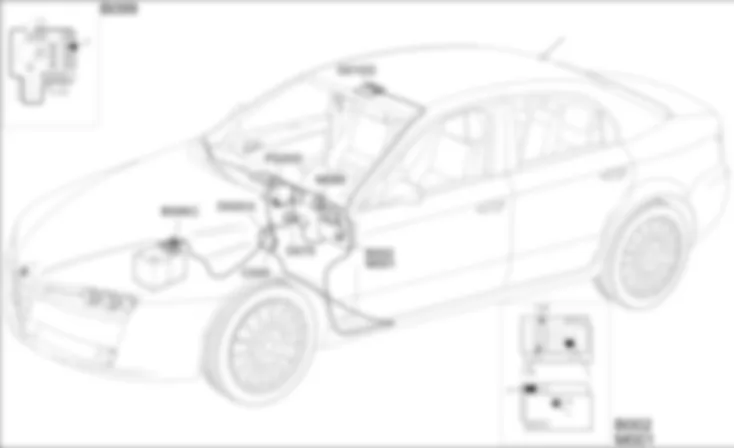
COMPONENT LOCATION - PREPARATION FOR CELLULAR TELEPHONE - Alfa Romeo 159 1.8 Da 01/06
| Component code | Description | Reference to the operation |
| B002 | JUNCTION UNIT UNDER DASHBOARD | |
| B099 | MAXIFUSE BOX ON BATTERY | |
| C020 | PASSENGER SIDE DASHBOARD EARTH | - |
| D020 | DASHBOARD/REAR COUPLING | - |
| D075 | RADIO PHONE COUPLING | - |
| G010 | FRONT COURTESY LIGHT | |
| M001 | BODY COMPUTER | |
| M089 | STEERING LOCK CONTROL UNIT (NBS) | |
| P020 | RADIO |
DESCRIPTION - PREPARATION FOR CELLULAR TELEPHONE - Alfa Romeo 159 1.8 Da 01/06
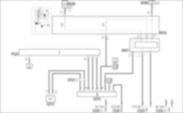
The vehicle is available, on request, not equipped with a CONNECT NAV + system - it can be supplied with provision for installing a cell phone.The system includes:- connection for a cell phone;- hands free function via the radio speakers;- external GSM aerial;- microphone located in the front courtesy light.The connection for the telephone, located at the base of the centre console, includes all the power supplies and signals needed for the operation of the telephone.The stylus aerial is fitted at the rear of the roof: it is a two-function aerial with two leads: one is the actual radio aerial used by the radio, one is the cable for the dual band reception telephone (GSM-ETACS at 900 Hz and D.C.S. at 1800 Hz).The radio receives input audio signals from the telephone connection; the sound of the telephone always arrives at a fixed volume which can, however, be adjusted in the radio menu function.The operation of the telephone switches off the radio temporarily (MUTE function).The connection for the telephone has two power supplies; one direct and one with the ignition ON: the above two lines are protected by two fuses in the junction unit under the dashboard; there is also a power supply with the side lights on to light up the telephone
FUNCTIONAL DESCRIPTION - PREPARATION FOR CELLULAR TELEPHONE - Alfa Romeo 159 1.8 Da 01/06
The connection D75 receives the direct supply - pin 9 - from the battery via the line for fuse F39 of the junction unit under the dashboard B2 (this power supply "passes through" the Body Computer M1, pin 26 of connector H).It receives an ignition-controlled power supply (INT) - pin 7 - via the line for fuse F49 of junction unit B2 .The power supply with the side lights on reaches pin 8 coming from the Body Computer M1, pin 18 of connector H: the telephone, if fitted, is lit up like the other controlsPin 10 of connector D75 is earthed.Pins 4 and 3 of D75 provide the audio signal (+ and - respectively) for the radio P20 - pins 7 and 8 of connector D, which then controls the speakers.Pin 1 of D75 is also connected to the radio P20, pin 9 of connector D (MUTE function).The hands free microphone located in the front courtesy light G10 - connector D - is connected to pins 5 and 6 of D75.
 Deutsch
 English
 English
 Español
 Français
 Nederlands
 Русский

