Hummer H3 2007 - 2007 GENERAL MOTORS H3
Hummer H3 2007 - BUZZERS, RELAYS & TIMERS
Hummer H3 2007 BUZZERS, RELAYS & TIMERS LOCATION
Component Location A/C CLUTCH Relay In underhood fuse block. See Fig. 60. AIR SOL Relay In underhood fuse block. See Fig. 60. FOG/LP Relay In underhood fuse block. See Fig. 60. FUEL/PUMP Relay In underhood fuse block. See Fig. 60. Grille Lamps Relay Below side air inlet cover. HDLP Relay In underhood fuse block. See Fig. 60. High Speed Blower Motor Relay Attached to blower motor case. See Fig. 24. HI/LO BEAM Relay In underhood fuse block. See Fig. 60. HI/LOW WPR Relay In underhood fuse block. See Fig. 60. HORN Relay In underhood fuse block. See Fig. 60. HVAC Relay In underhood fuse block. See Fig. 60. ON/OFF WPR Relay In underhood fuse block. See Fig. 60. PCM CNTRL Relay In underhood fuse block. See Fig. 60. PRK/LP Relay In underhood fuse block. See Fig. 60. PWR/TRN Relay In underhood fuse block. See Fig. 60. RAP/ACCY Relay In underhood fuse block. See Fig. 60. Roof Lamps Relay Below side air inlet cover. RR DEFOG Relay In underhood fuse block. See Fig. 60. RUN/CRNK Relay In underhood fuse block. See Fig. 60. SPARE-1 Relay In underhood fuse block. See Fig. 60. SPARE-2 Relay In underhood fuse block. See Fig. 60.
Hummer H3 2007 - CIRCUIT PROTECTION DEVICES
Hummer H3 2007 CIRCUIT PROTECTION DEVICES LOCATION
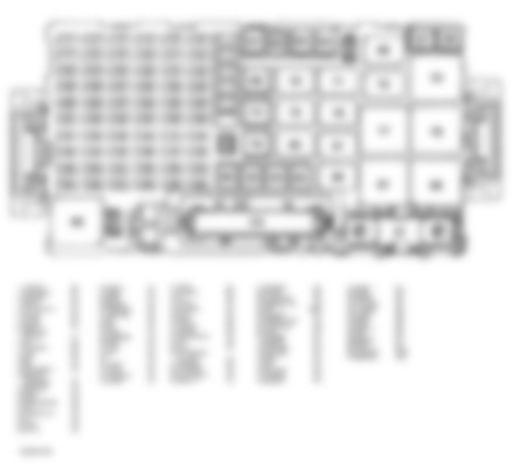
Component Location Underhood Fuse Block Above left front wheel well. See Fig. 14.
Hummer H3 2007 - CONTROL UNITS
Hummer H3 2007 CONTROL UNITS LOCATION
Component Location Automatic Transmission Floor Shift Control Beneath center console. See Fig. 31. Body Control Module (BCM) Behind right front kick panel. See Fig. 9. Electronic Brake Control Module (EBCM) Left of master cylinder. See Fig. 3. Heated Seat Module - Driver In driver seat bottom. See Fig. 44. Heated Seat Module - Passenger In passenger seat bottom. See Fig. 45. HVAC Module Beneath radio. See Fig. 24. Inflatable Restraint I/P Module Above dash compartment. See Fig. 1. Inflatable Restraint Passenger Presence System (PPS) Module On underside of cushion. See Fig. 45. Inflatable Restraint Roof Rail Module - Left Upper left "B" pillar. See Fig. 30. Inflatable Restraint Roof Rail Module - Right Upper right "B" pillar. See Fig. 30. Inflatable Restraint Sensing And Diagnostic Module (SDM) Beneath lower console. See Fig. 30. Inflatable Restraint Steering Wheel Module In steering column. See Fig. 1. Powertrain Control Module (PCM) At left front side of engine compartment. See Fig. 14. Transfer Case Shift Control Module Behind glove box. See Fig. 33. Vehicle Communication Interface Module (VCIM) Center of dash below HVAC control head. See Fig. 26.
Hummer H3 2007 - MOTORS
Hummer H3 2007 MOTORS LOCATION
Component Location Air Temperature Actuator - Left Mounted to left side of HVAC Module assembly. See Fig. 24. Air Temperature Actuator - Right Mounted to left side of HVAC Module assembly. See Fig. 24. Blower Motor Below right side of dash. See Fig. 24. Door Lock Actuator - Driver In center rear of driver door, near door latch. See Fig. 10. Door Lock Actuator - Endgate On right side of endgate. See Fig. 13. Door Lock Actuator - LR In center rear of left rear door, near door latch. See Fig. 12. Door Lock Actuator - Passenger In center rear of passenger door, near door latch. See Fig. 11. Door Lock Actuator - RR In center rear of right rear door, near door latch. See Fig. 43. Fuel Pump And Sender Assembly Mounted on top of fuel tank. See Fig. 18. Ignition Lock Cylinder Control Actuator On upper right side of steering column. See Fig. 29. Lumbar Pump Motor - Driver In driver seat. See Fig. 44. Lumbar Pump Motor - Passenger In passenger seat. See Fig. 45. Mode Actuator On side of heater box. See Fig. 24. Rear Differential Lock Actuator Mounted to center of rear axle. See Fig. 48. Rear Window Washer Fluid Pump In right rear engine compartment area. See Fig. 34. Rear Window Wiper Motor Center of endgate. See Fig. 13. Recirculation Actuator Upper right corner of heater case. See Fig. 24. Seat Motors - Driver Under driver seat. See Fig. 44. Seat Motors - Passenger Under passenger seat. See Fig. 45. Starter Motor Mounted to left side of engine. See Fig. 19. Sunroof Motor At front of sunroof module. See Fig. 22. Transfer Case Encoder Motor Part of transfer case. Window Motor - Driver Attached to interior of left front door. See Fig. 10. Window Motor - LR Attached to interior of left rear door. See Fig. 12. Window Motor - Passenger Attached to interior of right front door. See Fig. 11. Window Motor - RR Attached to interior of right rear door. See Fig. 43. Windshield Washer Fluid Pump Mounted on fluid reservoir. See Fig. 34. Windshield Wiper Motor Under center of front cowling. See Fig. 34.
Hummer H3 2007 - SENDING UNITS & SENSORS
Hummer H3 2007 SENDING UNITS & SENSORS LOCATION
Component Location Accelerator Pedal Position (APP) Sensor On accelerator pedal bracket. See Fig. 2. A/C Refrigerant Pressure Sensor On high pressure hose connection to compressor. See Fig. 23. Ambient Air Temperature Sensor Attached to front center of radiator support. See Fig. 23. Ambient Light Sensor Right side of dash upper trim panel. See Fig. 1. Camshaft Position (CMP) Sensor - Exhaust Top right front of engine. See Fig. 16. Camshaft Position (CMP) Sensor - Intake Top front left of engine. See Fig. 16. Crankshaft Position (CKP) Sensor Left rear of engine block, below starter. See Fig. 16. Engine Coolant Temperature (ECT) Sensor Front left of engine. See Fig. 15. Evaporator Temperature Sensor Behind right lower dash. See Fig. 24. Fuel Tank Pressure (FTP) Sensor Top of fuel pump and sender assembly. Heated Oxygen Sensor (HO2S) 1 On exhaust manifold on left side of engine. See Fig. 15. Heated Oxygen Sensor (HO2S) 2 In exhaust pipe, adjacent to transmission. See Fig. 6. Inflatable Restraint Front End Sensor - Left Left lower radiator support. See Fig. 23. Inflatable Restraint Front End Sensor - Right Right lower radiator support. See Fig. 23. Inflatable Restraint Passenger Presence System (PPS) Sensor In front passenger seat cushion. See Fig. 45. Inflatable Restraint Passenger Seat Belt Tension Sensor Part of seat belt buckle. Inflatable Restraint Seat Position Sensor (SPS) - Left On driver seat track. See Fig. 44. Inflatable Restraint Seat Position Sensor (SPS) - Right On driver seat track. See Fig. 45. Inflatable Restraint Side Impact Sensor (SIS) - Left In left front door. See Fig. 10. Inflatable Restraint Side Impact Sensor (SIS) - Right In right front door. See Fig. 11. Inflatable Restraint Vehicle Rollover Sensor Under center console. See Fig. 3. Input Speed Sensor (ISS) Assembly On transmission assembly. See Fig. 5. Knock Sensor (KS) Bank 2 Below intake manifold, near front of engine. See Fig. 16. Longitudinal Accelerometer Sensor Under driver seat near C307. See Fig. 46. Manifold Absolute Pressure (MAP) Sensor At top right side rear of engine, on intake manifold. See Fig. 15. Mass Air Flow (MAF)/Intake Air Temperature (IAT) Sensor Between air cleaner and throttle body. See Fig. 14. Steering Wheel Position Sensor Near base of steering column. See Fig. 29. Tire Pressure Monitor Sensors In respective tire. See Fig. 32. Vehicle Speed Sensor (VSS) Left rear of transfer case. See Fig. 5. Wheel Speed Sensor (WSS) - LF Attached to left front wheel hub. See Fig. 4. Wheel Speed Sensor (WSS) - LR Attached to left side of rear axle. See Fig. 4. Wheel Speed Sensor (WSS) - RF Attached to right front wheel hub. See Fig. 4. Wheel Speed Sensor (WSS) - RR Attached to right side of rear axle. See Fig. 4. Yaw Rate/Lateral & Longitudinal Accelerometer Sensor Under driver seat near C307. See Fig. 3.
Hummer H3 2007 - SOLENOIDS & SOLENOID VALVES
Hummer H3 2007 SOLENOIDS & SOLENOID VALVES LOCATION
Component Location A/C Compressor Clutch Part of A/C compressor. See Fig. 23. A/T Shift Lock Control Solenoid Part of automatic transmission floor shift control. See Fig. 31. Camshaft Position (CMP) Actuator Solenoid (Bank 1 Exhaust) Right front of cylinder head. See Fig. 15. Evaporative Emission (EVAP) Canister Purge Solenoid Valve Below intake, in back of alternator. See Fig. 16. Evaporative Emission (EVAP) Canister Vent Solenoid Valve Above spare tire. See Fig. 18. Fuel Injector 1 Attached to fuel rail at No. 1 cylinder. See Fig. 17. Fuel Injector 2 Attached to fuel rail at No. 2 cylinder. See Fig. 17. Fuel Injector 3 Attached to fuel rail at No. 3 cylinder. See Fig. 17. Fuel Injector 4 Attached to fuel rail at No. 4 cylinder. See Fig. 17. Fuel Injector 5 Attached to fuel rail at No. 5 cylinder. See Fig. 17. Pressure Control (PC) Solenoid Valve In automatic transmission. See Fig. 5. Torque Converter Clutch Pulse Width Modulation (TCC PWM) Solenoid Valve In automatic transmission. See Fig. 5. Torque Converter Clutch (TCC) Solenoid Valve In automatic transmission. See Fig. 5. 1-2 Shift Solenoid (SS) Valve In automatic transmission. See Fig. 5. 2-3 Shift Solenoid (SS) Valve In automatic transmission. See Fig. 5. 3-2 Shift Solenoid (SS) Valve In automatic transmission. See Fig. 5.
Hummer H3 2007 - SWITCHES
Hummer H3 2007 SWITCHES LOCATION
Component Location Automatic Transmission Fluid Pressure (TFP) Manual Valve Position Switch In automatic transmission. See Fig. 5. Backup Lamp Switch On top of transmission. See Fig. 28. Brake Fluid Level Switch On left side of brake fluid reservoir. See Fig. 3. Clutch Release Switch At top of clutch pedal assembly. See Fig. 20. Clutch Start Switch At top of clutch pedal assembly. See Fig. 2. Door Ajar Switch - Driver In lower left "B" pillar. See Fig. 27. Door Ajar Switch - LR In lower left "C" pillar. See Fig. 27. Door Ajar Switch - Passenger In lower right "B" pillar. See Fig. 27. Door Ajar Switch - RR In lower right "C" pillar. See Fig. 27. Endgate Ajar Switch In right "D" pillar. See Fig. 27. Engine Oil Pressure (EOP) Switch Above oil filter. See Fig. 15. Ignition Switch Bottom center of steering column. See Fig. 29. Park Brake Switch Left lower side of dash. See Fig. 2. Park/Neutral Position (PNP) Switch Left side of automatic transmission. See Fig. 47. Stop Lamp Switch Above brake pedal assembly. See Fig. 2. TCC Brake/Cruise Release Switch Top of brake pedal assembly. See Fig. 2.
Hummer H3 2007 - MISCELLANEOUS
Hummer H3 2007 MISCELLANEOUS LOCATION
Component Location Audio Amplifier Mounted next to subwoofer. See Fig. 21. Battery Left side of engine compartment. See Fig. 42. Blower Motor Resistor Assembly Attached to bottom of blower. See Fig. 24. Cellular Microphone Mounted in left front headliner. See Fig. 8. Cellular, Navigation & Digital Radio Antenna Mounted to right front roof area. See Fig. 7. Data Link Connector (DLC) Left side of dash. See Fig. 26. Digital Radio Receiver Right side of dash. See Fig. 26. Generator At left front of engine. See Fig. 19. Global Positioning System (GPS) Antenna Behind right dash cluster. Heater Element Seat Back - Driver In driver seat back. See Fig. 44. Heater Element Seat Back - Passenger In passenger seat back. See Fig. 45. Heater Element Seat Cushion - Driver In driver seat bottom. See Fig. 44. Heater Element Seat Cushion - Passenger In passenger seat bottom. See Fig. 45. Horn Front of vehicle, behind grill. See Fig. 25. Ignition Coil 1 In center front of cam cover at No. 1 cylinder. See Fig. 15. Ignition Coil 2 In center front of cam cover at No. 2 cylinder. See Fig. 15. Ignition Coil 3 In center front of cam cover at No. 3 cylinder. See Fig. 15. Ignition Coil 4 In center front of cam cover at No. 4 cylinder. See Fig. 15. Ignition Coil 5 In center front of cam cover at No. 5 cylinder. See Fig. 15. Inflatable Restraint Steering Wheel Module Coil Mounted to steering wheel. See Fig. 29. Seat Belt Pretensioner - LF At left inner "B" pillar. See Fig. 30. Seat Belt Pretensioner - RF At right inner "B" pillar. See Fig. 30. Seat Belt Switch - Left Part of seat belt buckle (Driver). Seat Belt Switch - Right Part of seat belt buckle (Passenger). Throttle Body Top of engine, mounted on upper air intake manifold. See Fig. 15. Trailer Connector Mounted on left side of trailer receiver, rear of vehicle. See Fig. 49.
Hummer H3 2007 - CONNECTORS
Hummer H3 2007 CONNECTORS LOCATION
Component Location C101 (Black, 6 Pin) Rear center of engine. See Fig. 15. C115 (Black, 16 Pin) Right of left front fog lamp. See Fig. 25. C116 (Black, 8 Pin) Behind left headlamp assembly. See Fig. 25. C117 (Black, 8 Pin) Behind right headlamp assembly. See Fig. 25. C125 (Black, 16 Pin) Near battery. See Fig. 50. C130 (Black, 2 Pin) In body harness to battery cable harness. See Fig. 38. C150 (Black, 16 Pin) Behind battery next to EBCM. See Fig. 38. C155 (Black, 4 Pin) Next to EBCM. See Fig. 38. C200 (Black, 40 Pin) Behind left of dash. See Fig. 51. C201 (Light Gray, 22 Pin) Base of steering column. See Fig. 51. C203 (White, 8 Pin) Near blower motor. See Fig. 37. C204 (Light Gray, 22 Pin) Behind right kick panel. See Fig. 9. C205 (White, 12 Pin) Near blower motor. See Fig. 37. C207 (White, 12 Pin) Behind left of dash. See Fig. 51. C208 (Yellow, 4 Pin) Behind left of dash. See Fig. 51. C275 (Yellow, 4 Pin) Next to C201. See Fig. 29. C307 (White, 8 Pin) Under driver seat. See Fig. 44. C308 (White, 4 Pin) In body harness to driver seat belt switch jumper harness. See Fig. 44. C315 (White, 12 Pin) Under passenger seat. See Fig. 45. C318 (Black, 4 Pin) In passenger seat bottom. See Fig. 45. C319 (Black, 4 Pin) In driver seat bottom. C320 (w/o Seat Heater) (White, 4 Pin) In body harness to passenger seat belt switch jumper harness. See Fig. 45. C320 (w/Seat Heater) (White, 8 Pin) In body harness to passenger seat belt switch jumper harness. See Fig. 45. C330 (White, 8 Pin) Behind upper left A-pillar trim panel. See Fig. 22. C335 (White, 6 Pin) Behind upper left A-pillar trim panel. See Fig. 22. C350 (White, 6 Pin) Behind right lower A-pillar trim. See Fig. 52. C370 (White, 12 Pin) In left rear passenger door. See Fig. 53. C380 (White, 12 Pin) In right rear passenger door. See Fig. 53. C410 (Black, 4 Pin) Behind right rear quarter trim panel near D-pillar. See Fig. 54. C420 (w/Heavy Duty harness) (Black, 16 Pin) Rearward of left wheel well. C420 (w/o Heavy Duty Harness) (Black, 4 Pin) Rearward of left wheel well. C430 (White, 4 Pin) Behind left rear quarter trim panel near D-pillar. See Fig. 54. C450 (White, 12 Pin) Behind left rear quarter trim panel near D-pillar. See Fig. 13. C500 (White, 30 Pin) In driver door. See Fig. 10. C510 (White, 8 Pin) Inside middle front of drivers door, near A-pillar. See Fig. 10. C600 (White, 30 Pin) Body harness to passenger door harness, in passenger door. See Fig. 52. C901 (White, 12 Pin) Left middle of end gate, near pass-through. See Fig. 13.
Hummer H3 2007 - GROUNDS
Hummer H3 2007 GROUNDS LOCATION
Component Location G100 In engine compartment, mounted to the LF inner fender, behind the battery. See Fig. 19. G102 On lower left side of engine block, rearward of G103. See Fig. 16. G103 On lower left side of engine block, forward of G102. See Fig. 16. G104 Left side of engine block, in front of starter. See Fig. 56. G105 On left inner front wheel well, behind battery. See Fig. 35. G106 On right inner front wheel well. See Fig. 35. G110 Left side of engine block, forward of G103. See Fig. 56. G120 On left lower inner wheel well, near engine mount. See Fig. 56. G300 Under driver seat carpet, on floor board. See Fig. 35. G310 Mounted under left side of passenger seat. See Fig. 35. G320 Under rear of middle console carpet, on floor board. See Fig. 35. G340 Behind right rear quarter trim, near wheel well. See Fig. 54. G345 Behind left rear quarter trim, near wheel well. See Fig. 54. G350 Behind left rear quarter trim, near wheel well. See Fig. 54. G420 Mounted to left side of rear cross member, near C420. See Fig. 55.
Hummer H3 2007 - SPLICES
Hummer H3 2007 SPLICES LOCATION
Component Location S101 In dealer installed off road harness, 1.5cm (5.9in) from roof lamps relay, near master cylinder. S102 In dealer installed off road harness, 1.5cm (5.9in) from roof lamps relay, near master cylinder. S103 In engine compartment harness, near grille lamps relay, by master cylinder. S104 In dealer installed grille lamps off road harness, near left side grille lamp connector. S105 In dealer installed grille lamps off road harness, near left side grille lamp connector. S109 In forward lamp harness, approximately 43 cm (17 in) from C115. See Fig. 25. S110 In body harness near EBCM, approximately 7.5 cm (3 in) back from EBCM. See Fig. 38. S112 In forward lamp harness, near left upper radiator support, approximately 48.5 cm (19.1 in) from C115. See Fig. 25. S120 In forward lamp harness, near center point of top of radiator, approximately 58 cm (22.8 in) from C115. See Fig. 25. S134 In forward lamp harness, approximately 15 cm (5.9 in) from C115. See Fig. 25. S141 In body harness, approximately 5 cm (0.2 in) before breakout to EBCM. See Fig. 38. S143 In body harness, approximately 2 cm (0.8 in) before breakout to C125. See Fig. 38. S185 In forward lamp harness, approximately 25 cm (9.8 in) from C115. See Fig. 25. S205 In I/P harness, approximately 5 cm (2 in) right of breakout to left footwell lamp. See Fig. 36. S206 In I/P harness, approximately 7 cm (2.8 in) right of breakout to right footwell lamp. See Fig. 36. S209 In body harness, approximately 6 cm (2.4 in) to right of stop lamp switch breakout in main harness. See Fig. 58. S210 In body harness, approximately 16 cm (6.3 in) before left front tweeter breakout. See Fig. 58. S213 In body harness, approximately 11 cm (4.3 in) to right of stop lamp switch breakout in main harness. See Fig. 58. S214 In I/P harness, approximately 2.5 cm (1 in) to right of data link connector in main bundle. See Fig. 36. S215 In body harness, approximately 14 cm (5.5 in) to right of stop lamp switch breakout in main harness. See Fig. 58. S220 In blower motor resistor jumper harness, approximately 15 cm (6 in) from C203. See Fig. 37. S224 In body harness, approximately 15 cm (5.9 in) from main harness into breakout to sunroof. See Fig. 58. S230 In HVAC harness, approximately 10 cm (3.9 in) back from right air temperature actuator connector. See Fig. 37. S234 In I/P harness center dash area, approximately 5 cm (2 in) left of breakouts to HVAC in main bundle. See Fig. 36. S240 In HVAC harness, approximately 28.5 cm (11.2 in) back from right air temperature actuator connector. See Fig. 37. S244 In body harness behind passenger side dash area, approximately 25 cm (9.8 in) before breakout to right front door. See Fig. 58. S245 In body harness left front kick panel area, approximately 26 cm (10.2 in) rearward of left body pass through. S247 In body harness behind passenger side dash area, approximately 5 cm (2 in) before breakout to right front door. See Fig. 58. S250 In HVAC harness, approximately 13.5 cm (5.3 in) before breakout to evaporator temperature sensor. See Fig. 37. S251 In I/P harness, approximately 0.5 cm (0.2 in) right of breakout to left footwell lamp. See Fig. 36. S260 In HVAC harness, approximately 23.5 cm (9.3 in) back from right air temperature actuator connector. See Fig. 37. S264 In body harness, approximately 24.5 cm (9.6 in) rearward of body pass through in breakout to left door. S292 In body harness right kick panel area, approximately 3 cm (1.2 in) rearward of breakout to BCM. See Fig. 58. S294 In body harness, approximately 3 cm (1.2 in) to left of park brake switch breakout. See Fig. 58. S295 In body harness, approximately 3 cm (1.2 in) to right of park brake switch breakout. See Fig. 58. S300 In body harness, approximately 20 cm (7.9 in) forward of left rocker channel cover. S301 In dealer installed off road harness, under roof-mounted light bar near drivers side lamp connector. S302 In dealer installed off road harness, under roof-mounted light bar near drivers side lamp connector. S305 In body harness under right door sill plate, approximately 18 cm (7 in) from breakout to C204. See Fig. 57. S306 In driver seat harness in breakout to lumbar adjuster/heater switch. See Fig. 44. S309 In body harness under left door sill plate, approximately 41 cm (16.1 in) rearward of body pass through in main bundle. S310 In body harness, approximately 4.5 cm (1.8 in) left of breakout to A/T floor shift control. See Fig. 58. S312 In driver seat harness, approximately 28.5 cm (11.2 in) back from C307. See Fig. 44. S313 In passenger seat heater element jumper harness. S314 In body harness, approximately 44.5 cm (17.5 in) rearward of breakout to left seat belt pretensioner. See Fig. 57. S315 In body harness, approximately 47 cm (18.5 in) rearward of breakout to right seat belt pretensioner. See Fig. 57. S316 In passenger seat harness, approximately 5 cm (2 in) before breakout to seat adjuster and lumbar adjuster/heater switches. See Fig. 45. S317 In passenger seat heater element jumper harness. S318 In passenger seat heater element jumper harness. S319 In passenger seat heater element jumper harness. S320 In body harness rear seat area along sill, approximately 20 cm (7.9 in) rearward of breakout to G320. See Fig. 57. S321 In driver seat heater element jumper harness. S322 In driver seat heater element jumper harness. S323 In body harness, approximately 13 cm (5.1 in) right of breakout to G310. See Fig. 58. S324 In driver seat heater element jumper harness. S325 In driver seat heater element jumper harness. S330 In dome lamp jumper harness, approximately 5 cm (2 in) before breakout to right sunshade. See Fig. 39. S340 In dome lamp jumper harness, approximately 10 cm (3.9 in) before breakout to right sunshade. See Fig. 39. S341 In passenger seat harness, approximately 10 cm (3.9 in) before breakout to seat adjuster and lumbar adjuster/heater switches. See Fig. 45. S344 In body harness, approximately 20 cm (7 in) to left of SDM breakout. See Fig. 58. S347 In body harness, approximately 42 cm (16.5 in) rearward of breakout to right seat belt pretensioner. See Fig. 57. S350 In dome lamp jumper harness, approximately 5 cm (2 in) before breakout to dome/reading lamp. See Fig. 39. S359 In chassis harness, approximately 22.5 cm (8.9 in) from fuel pump and sender assembly connector. See Fig. 59. S514 In driver door harness, approximately 6.5 cm (2.6 in) before breakouts to door lock and window switch. See Fig. 40. S529 In driver door harness, approximately 7.5 cm (3 in) before breakout to power window motor. See Fig. 40. S590 In driver door harness, approximately 7.5 cm (3 in) before breakout to OSRVM. See Fig. 40. S900 In endgate harness, approximately 19.5 cm (7.7 in) rearward of endgate grommet. See Fig. 41.
Hummer H3 2007 - COMPONENT LOCATION GRAPHICS
NOTE:
Fig.res may show multiple component locations. - appropriate table for proper figure references.

Fig. 1: Hummer H3 2007 - Component Locations - Dash
Fig. 2: Hummer H3 2007 - Component Locations - Lower Left Side Of Dash
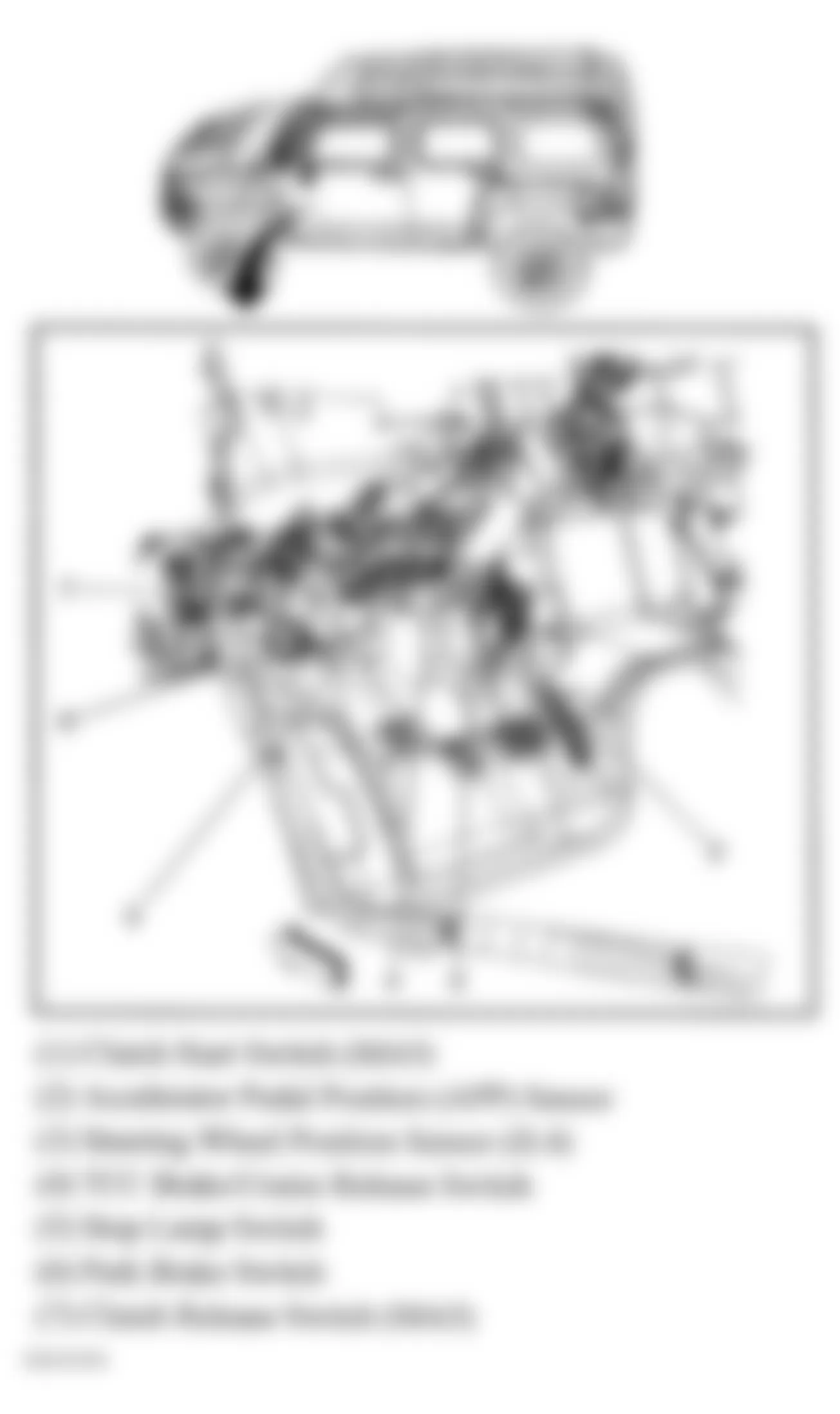
Fig. 3: Hummer H3 2007 - Component Locations - Brake Components
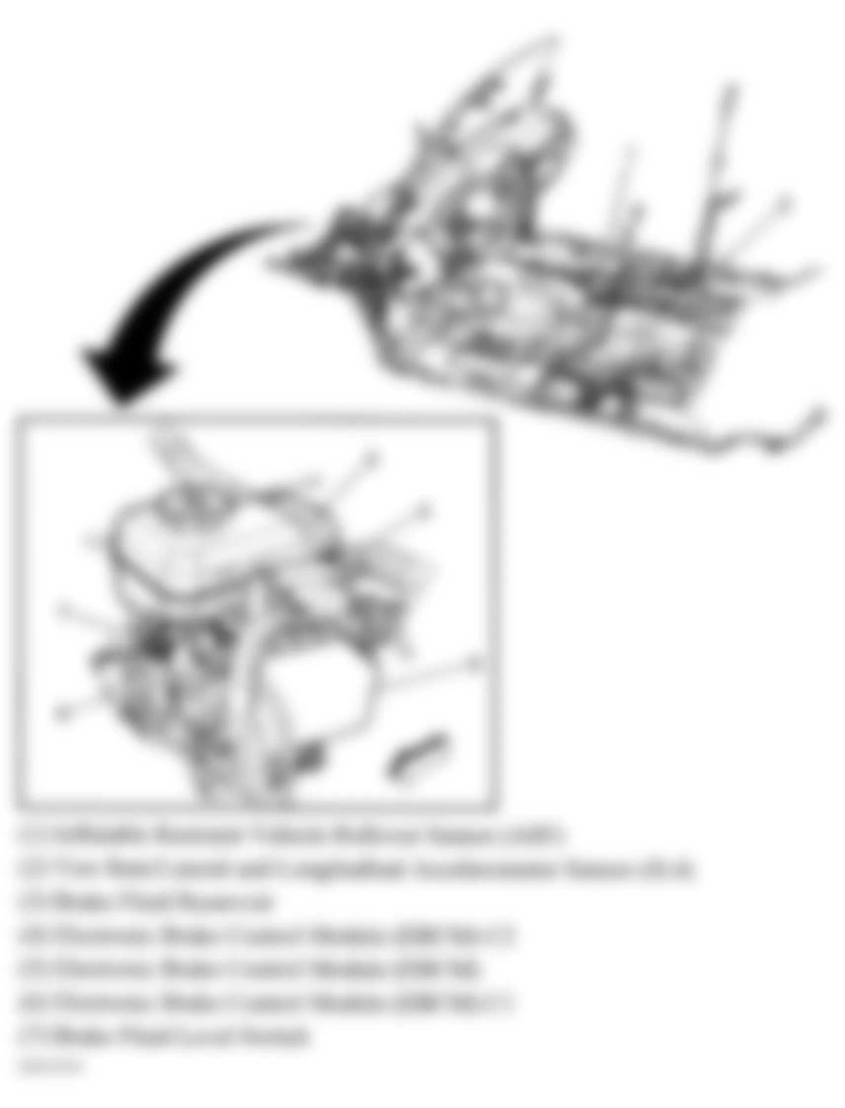
Fig. 4: Hummer H3 2007 - Component Locations - Wheel Speed Sensors
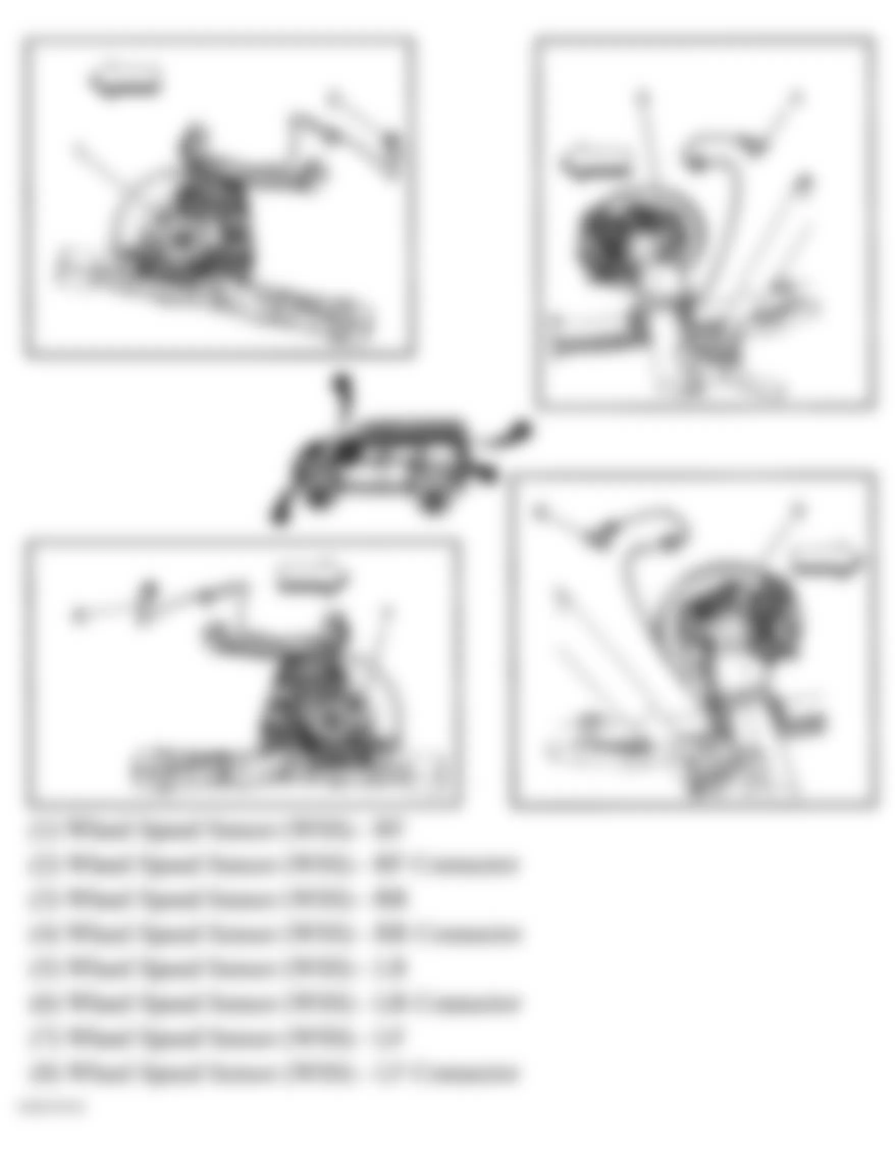
Fig. 5: Hummer H3 2007 - Component Locations - Transmission Assembly
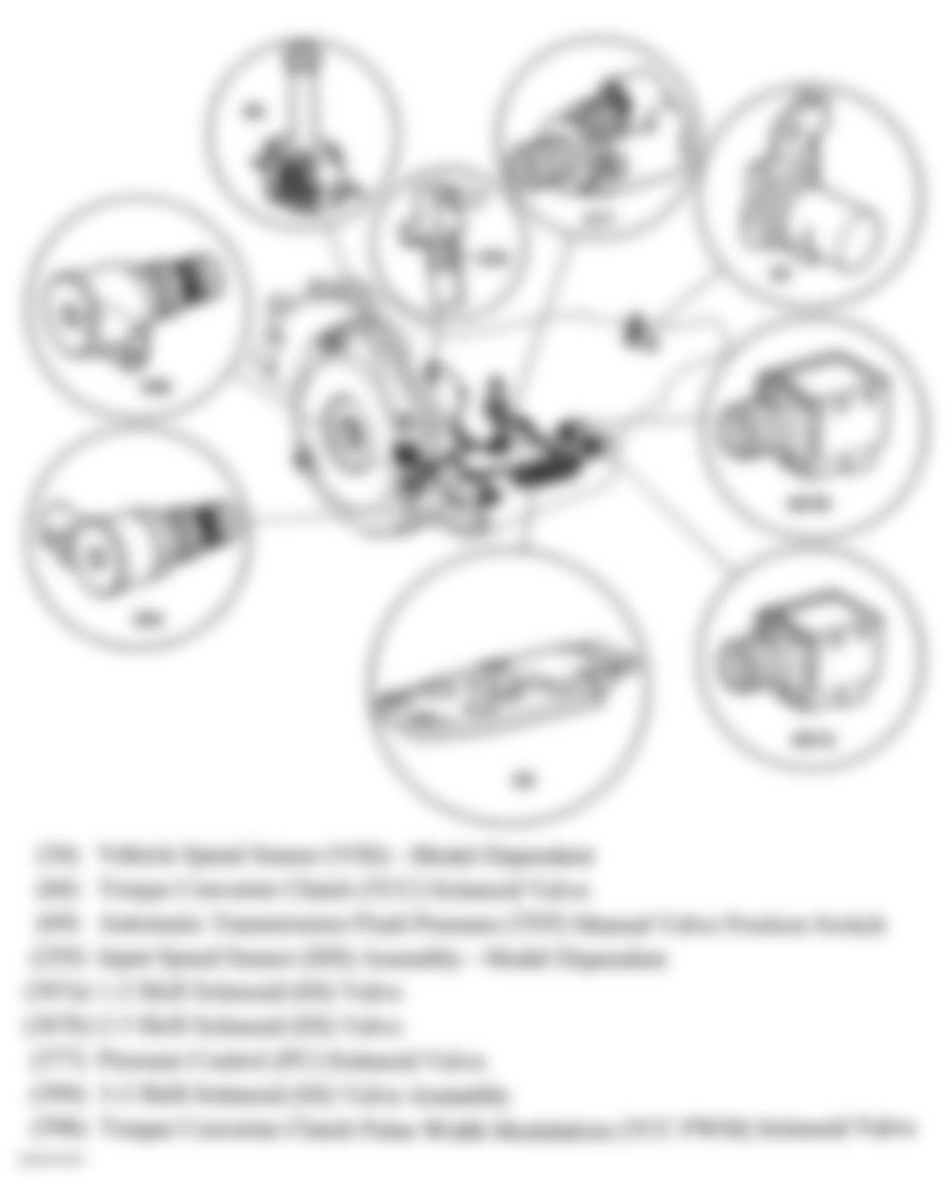
Fig. 6: Hummer H3 2007 - Component Locations - Transmission Assembly
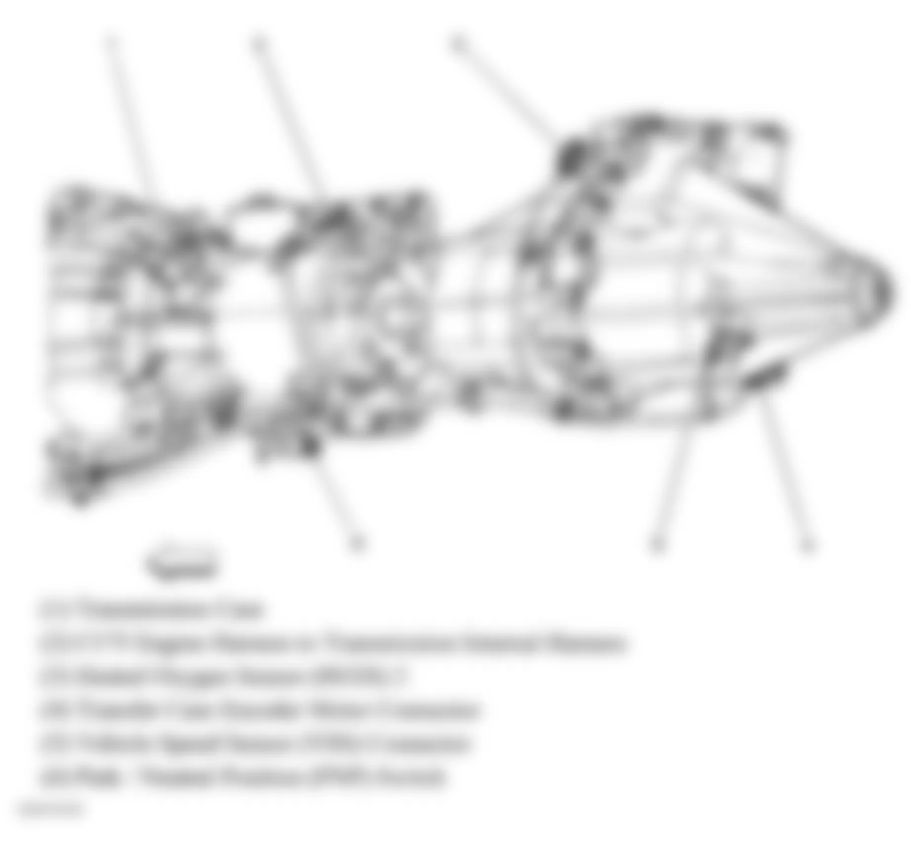
Fig. 7: Hummer H3 2007 - Component Locations - Entertainment Components
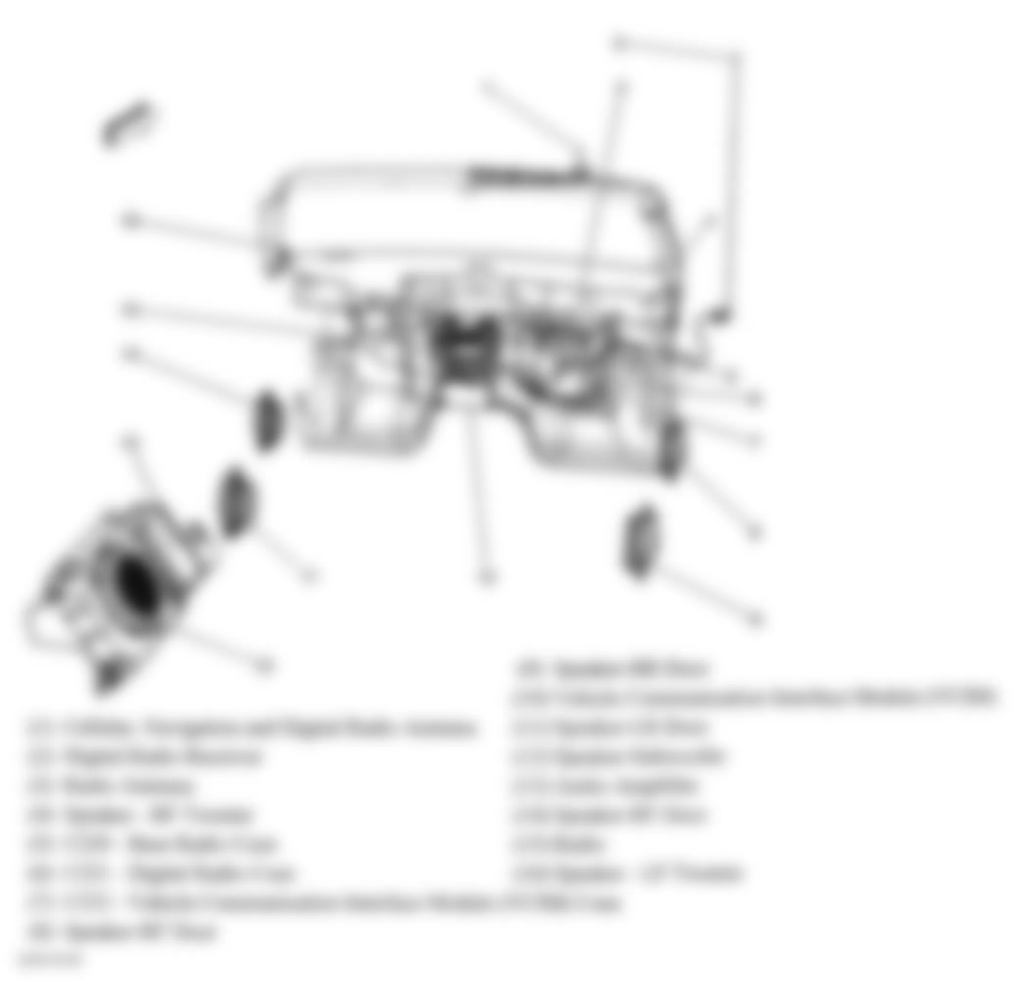
Fig. 8: Hummer H3 2007 - Component Locations - Headliner Components
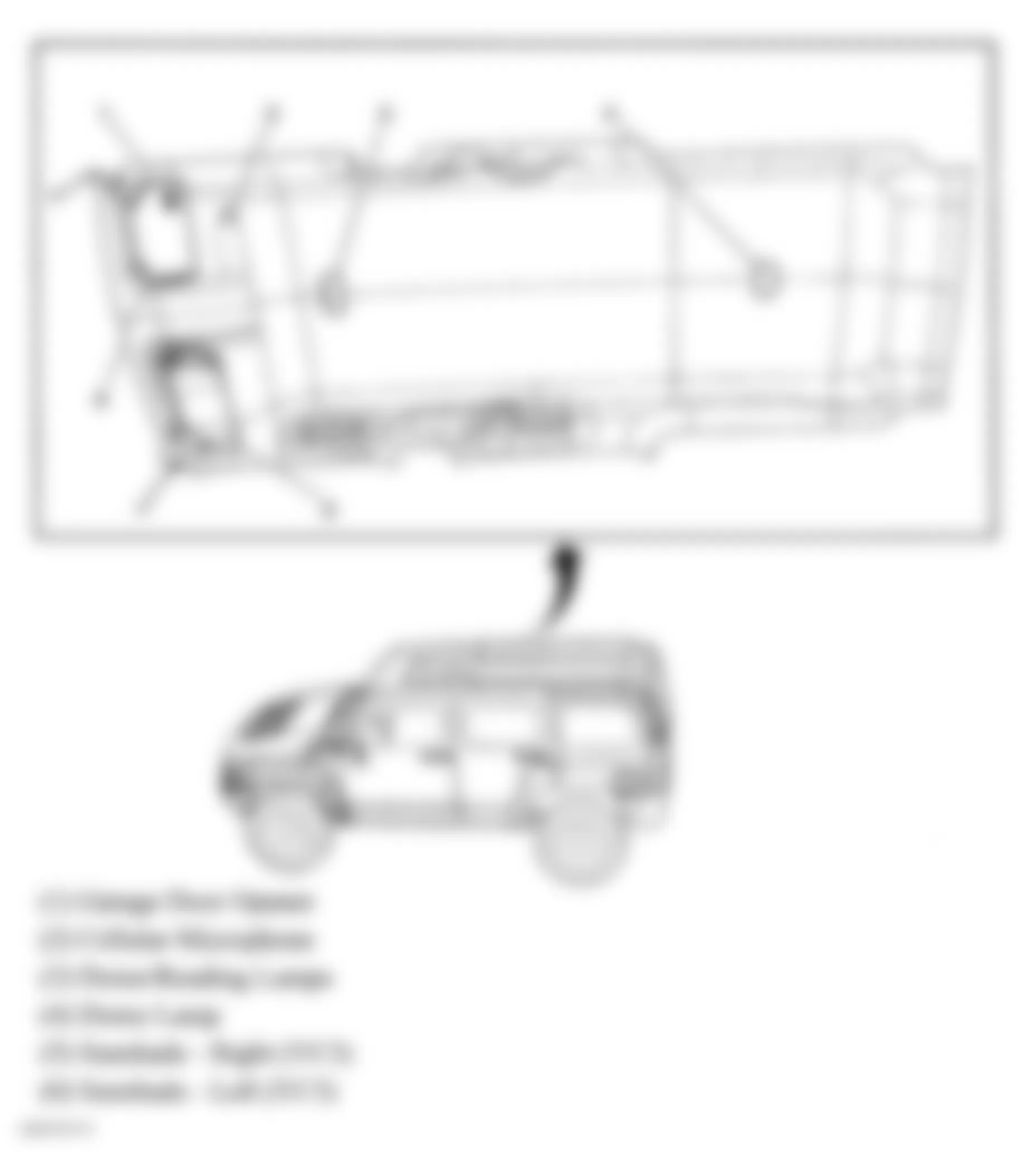
Fig. 9: Hummer H3 2007 - Component Locations - Right Front Kick Panel
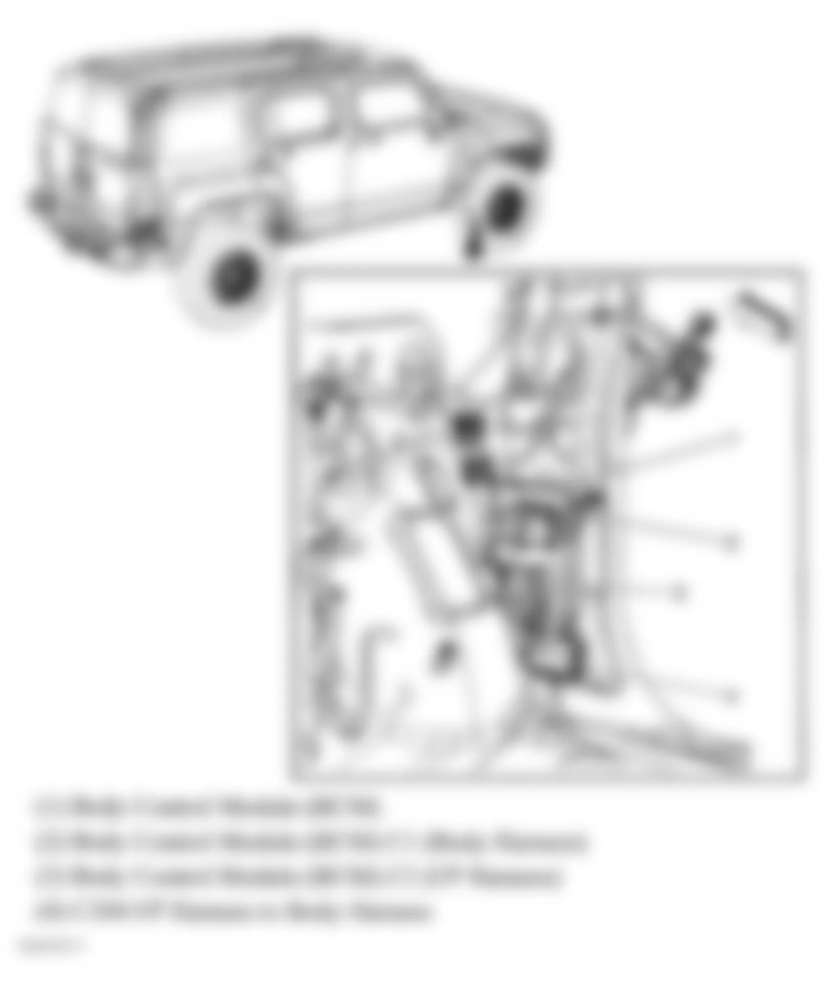
Fig. 10: Hummer H3 2007 - Component Locations - Driver Door
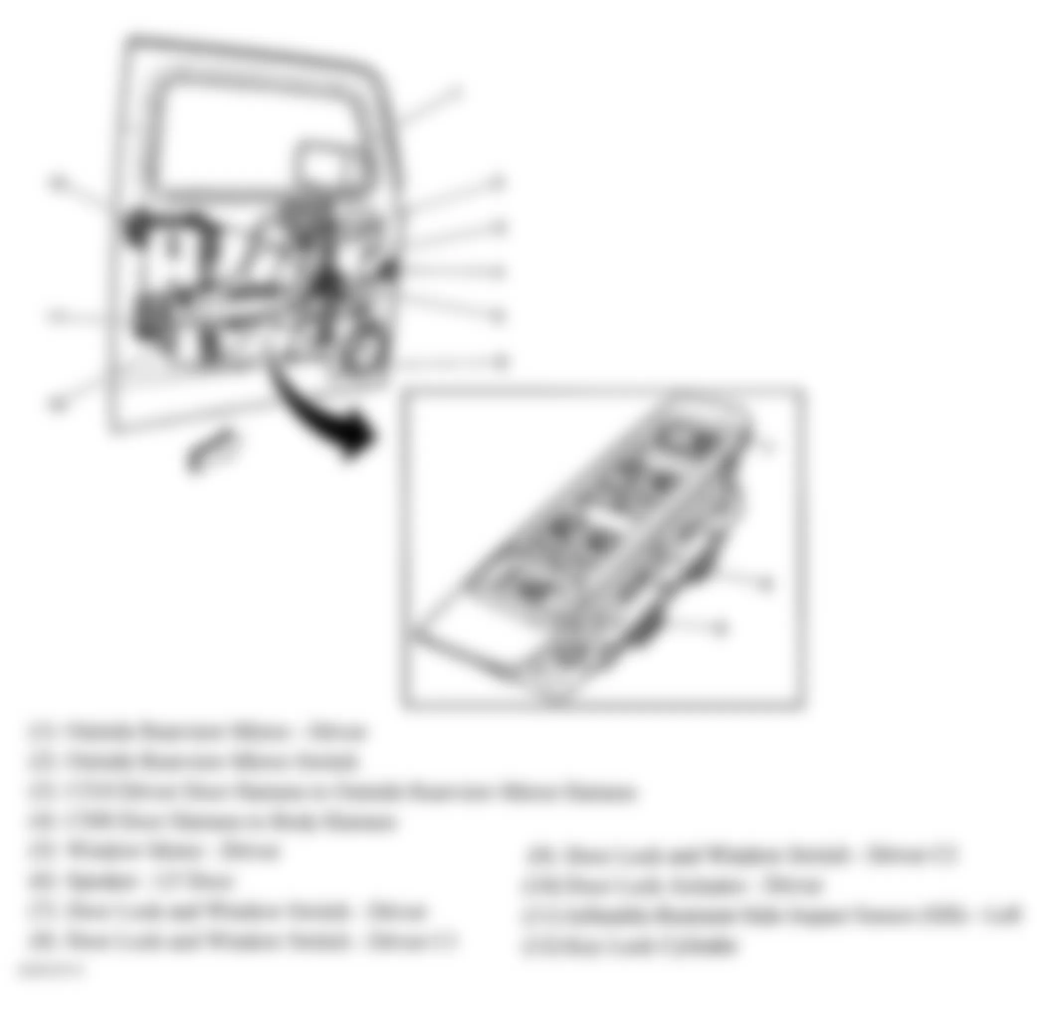
Fig. 11: Hummer H3 2007 - Component Locations - Front Passenger's Door
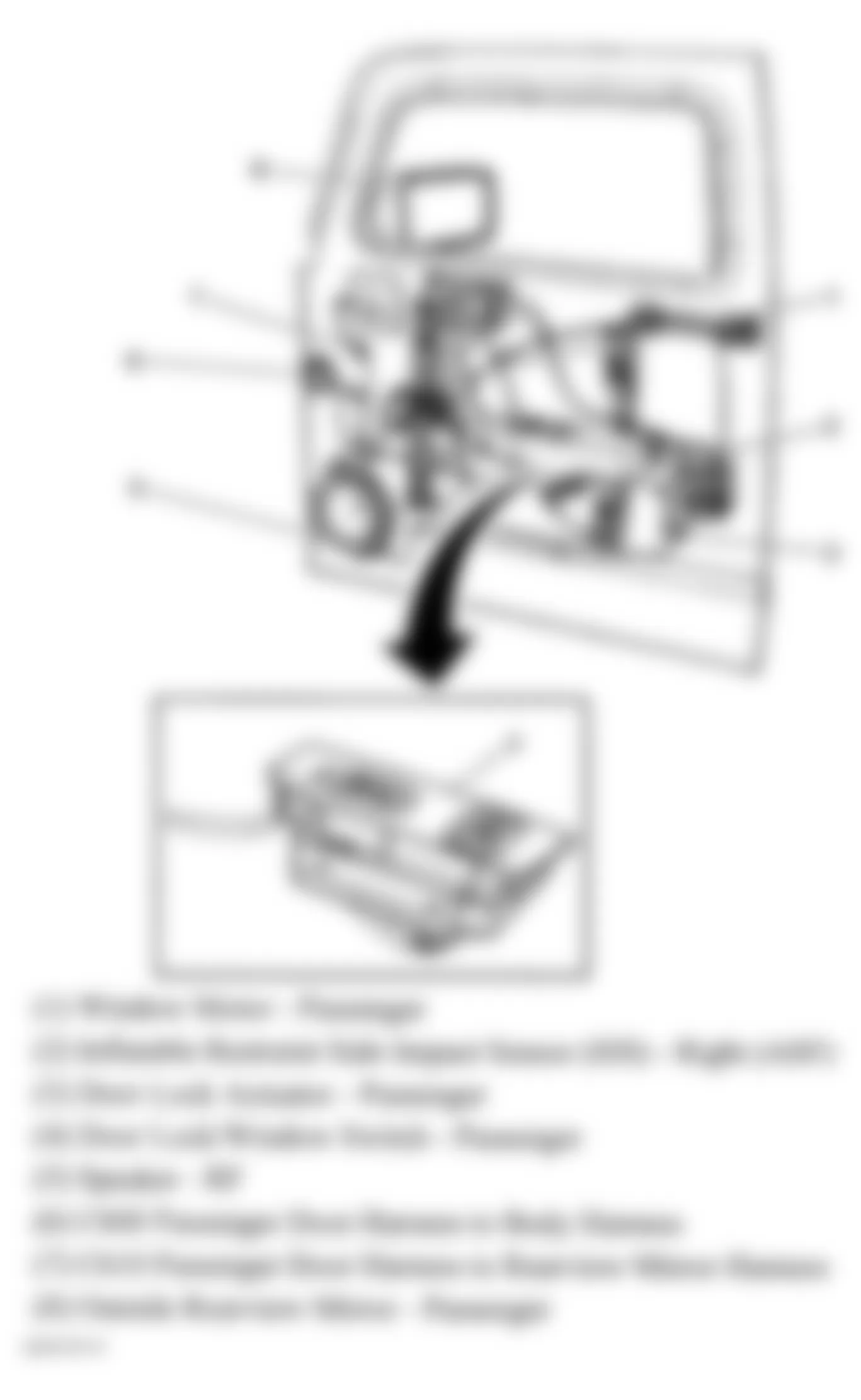
Fig. 12: Hummer H3 2007 - Component Locations - Left Rear Door
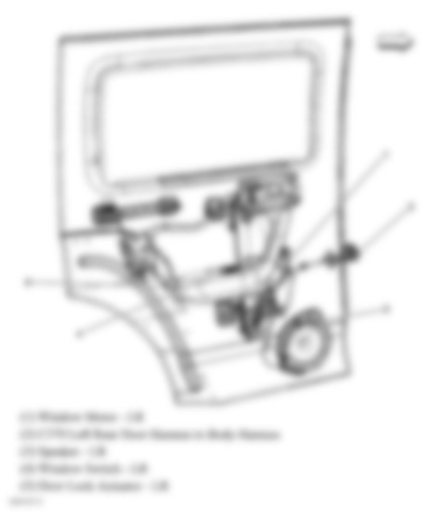
Fig. 13: Hummer H3 2007 - Component Locations - Endgate Components
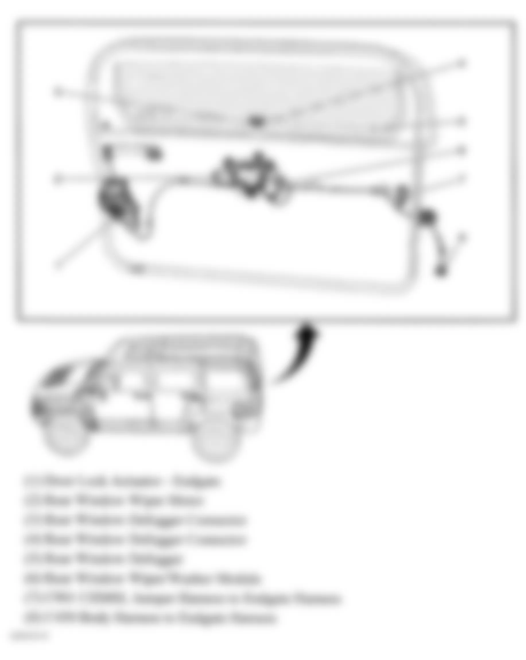
Fig. 14: Hummer H3 2007 - Component Locations - Engine Compartment
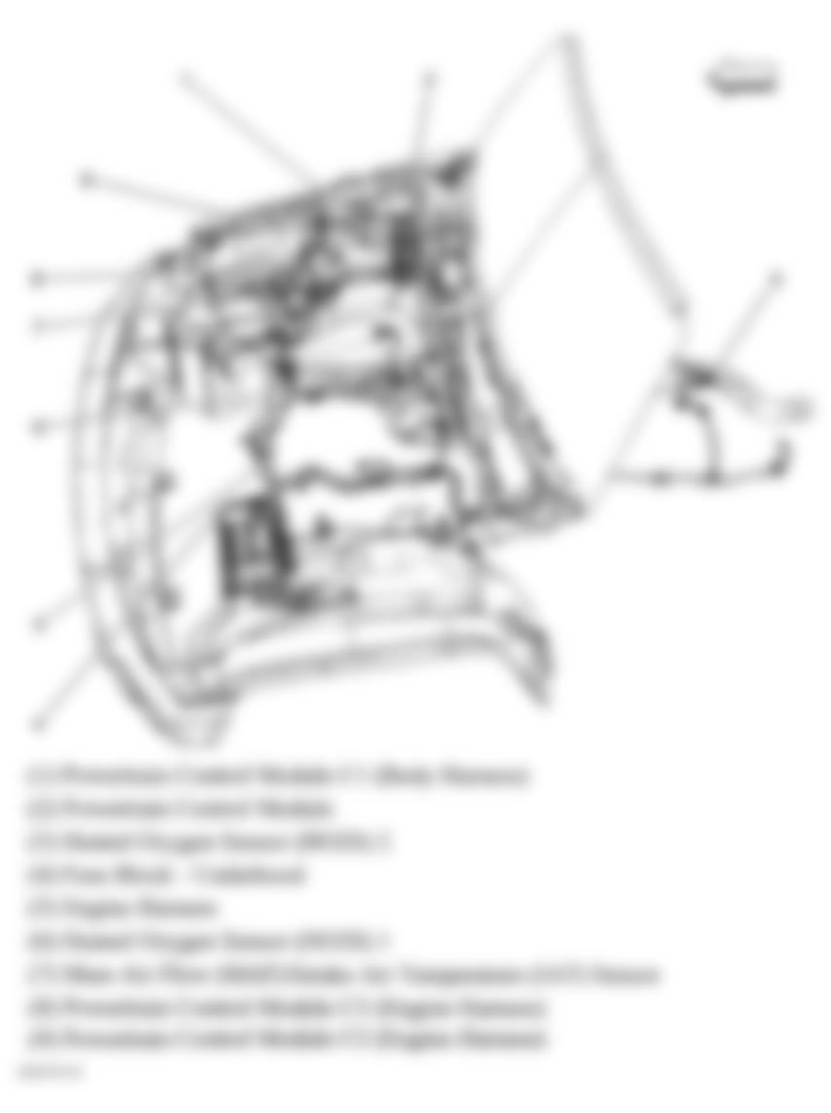
Fig. 15: Hummer H3 2007 - Component Locations - Right Side Of Engine Assembly
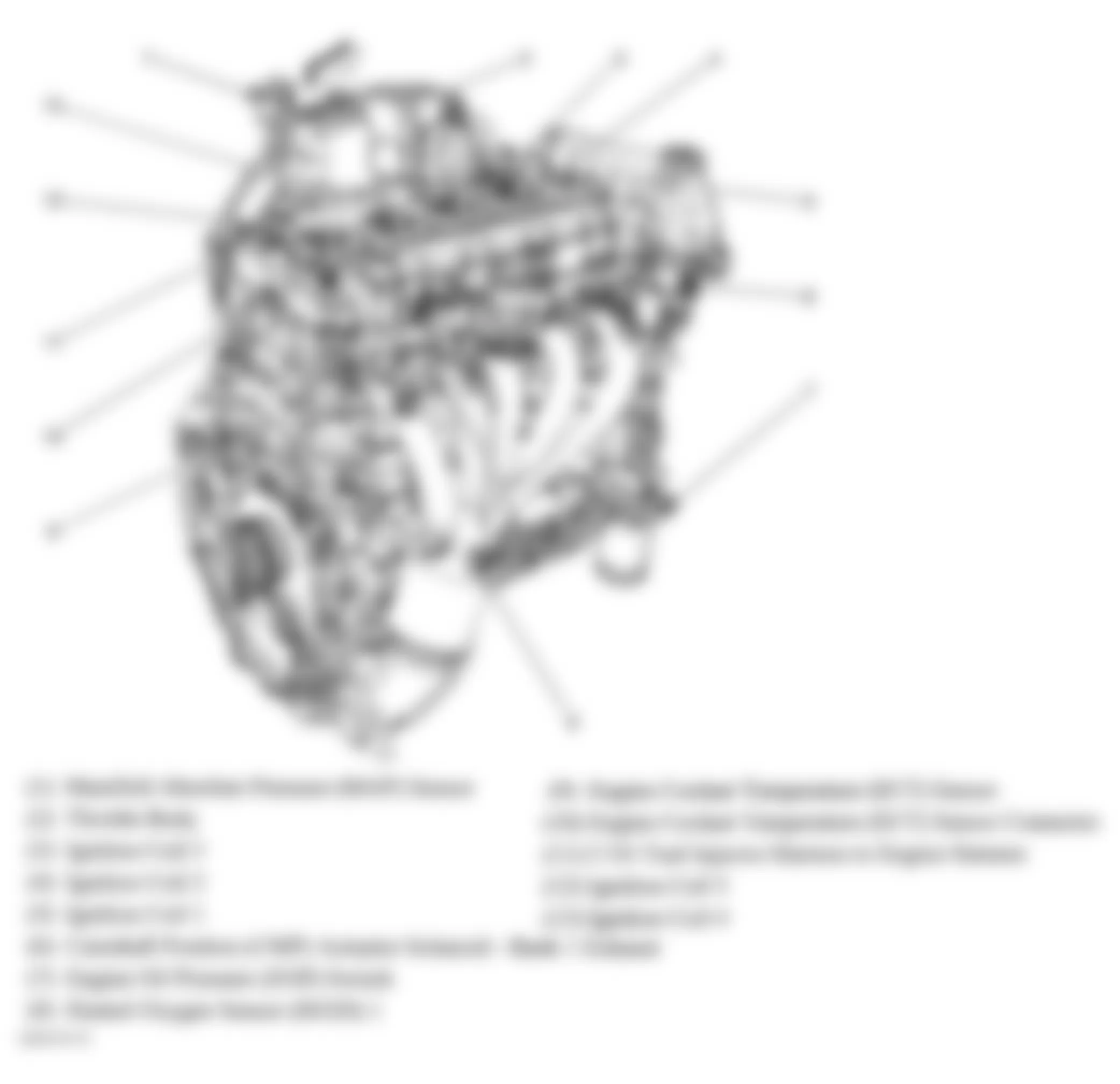
Fig. 16: Hummer H3 2007 - Component Locations - Left Side Of Engine
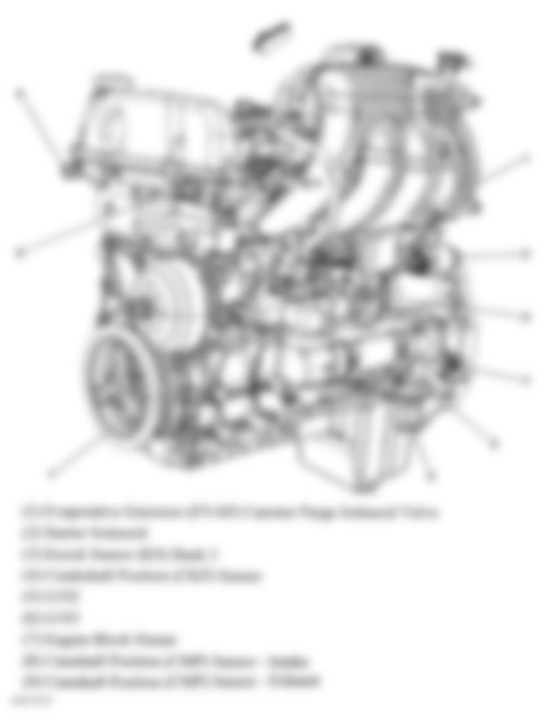
Fig. 17: Hummer H3 2007 - Component Locations - Top Of Engine
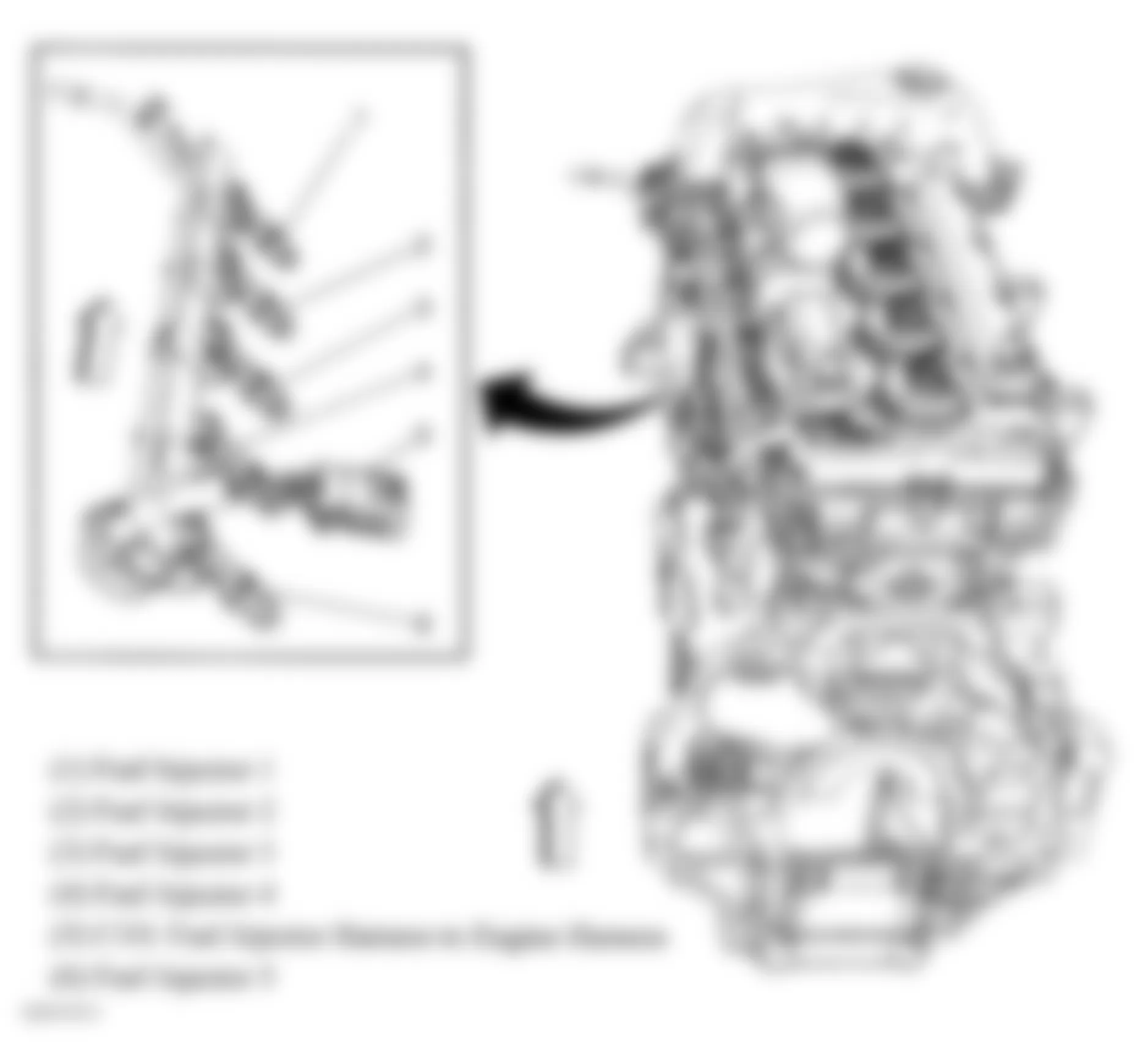
Fig. 18: Hummer H3 2007 - Component Locations - Frame Rail
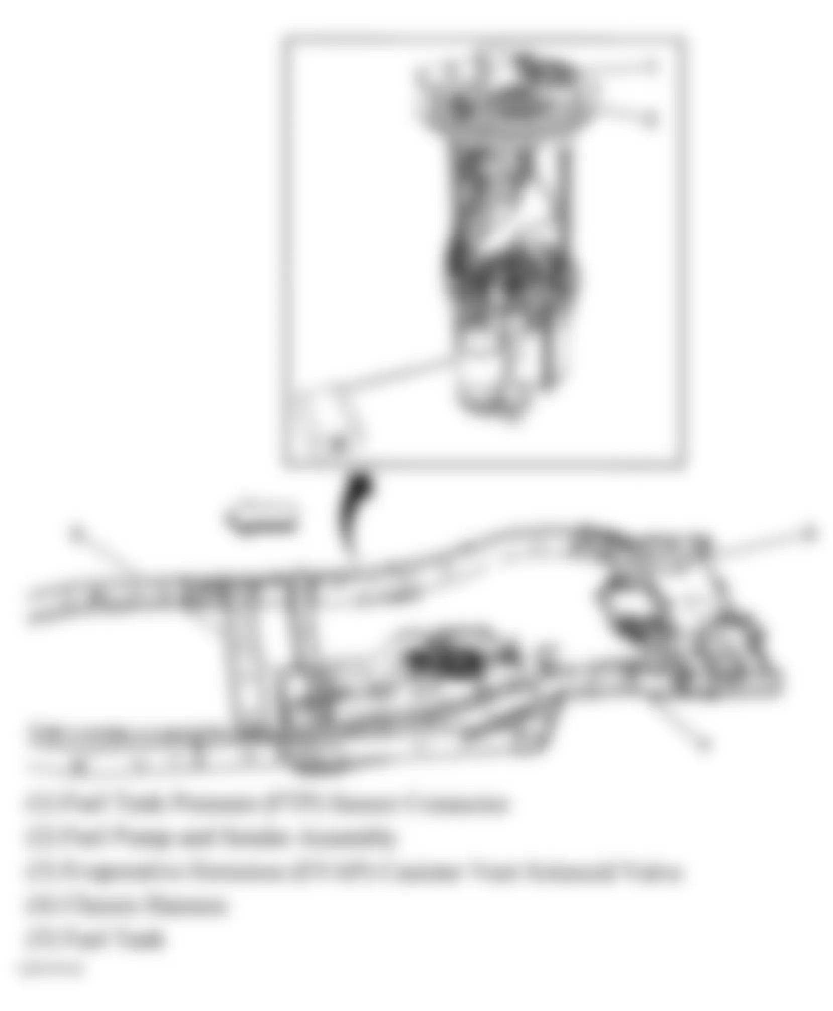
Fig. 19: Hummer H3 2007 - Component Locations - Engine Electrical Components
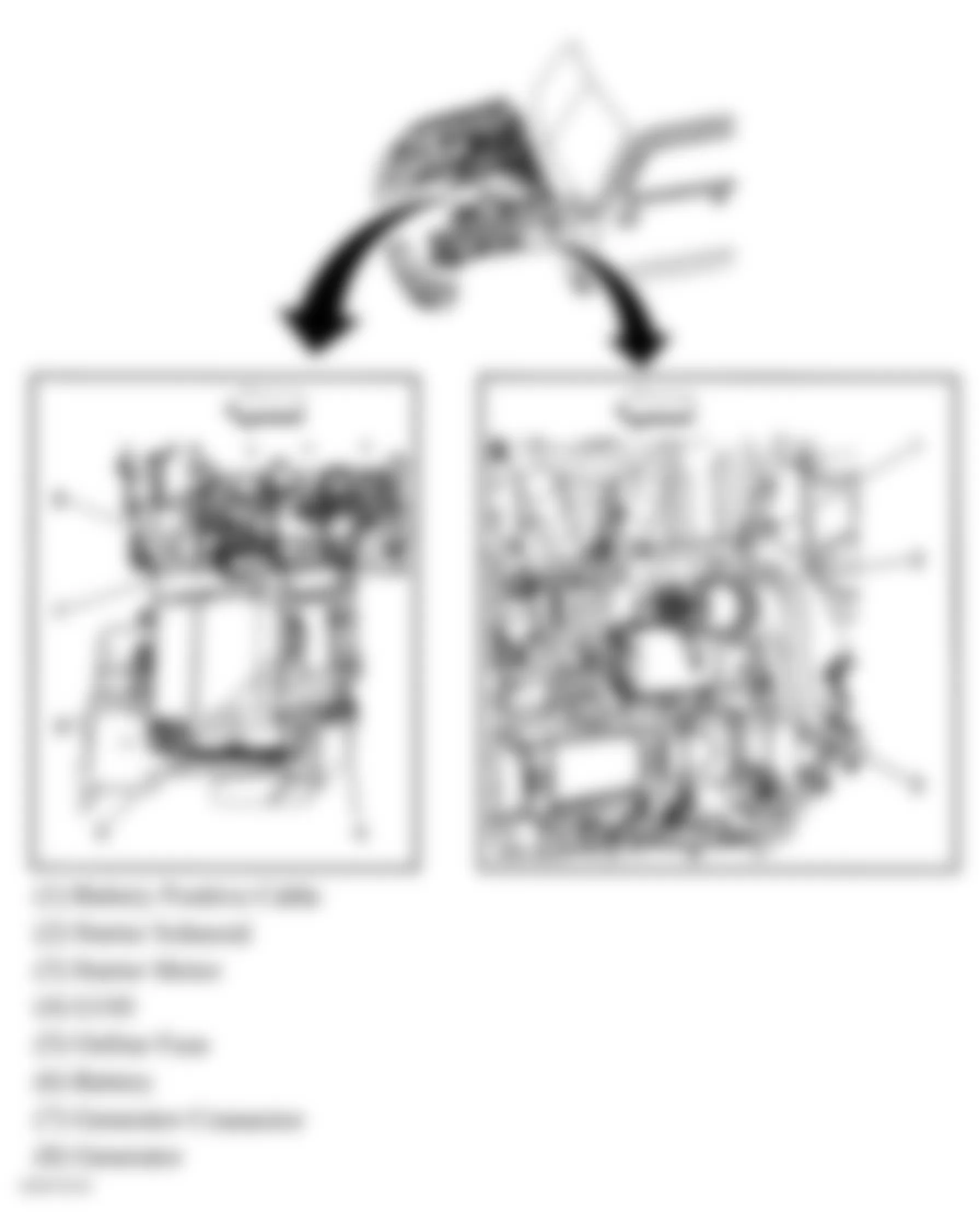
Fig. 20: Hummer H3 2007 - Component Locations - Engine Electrical Components
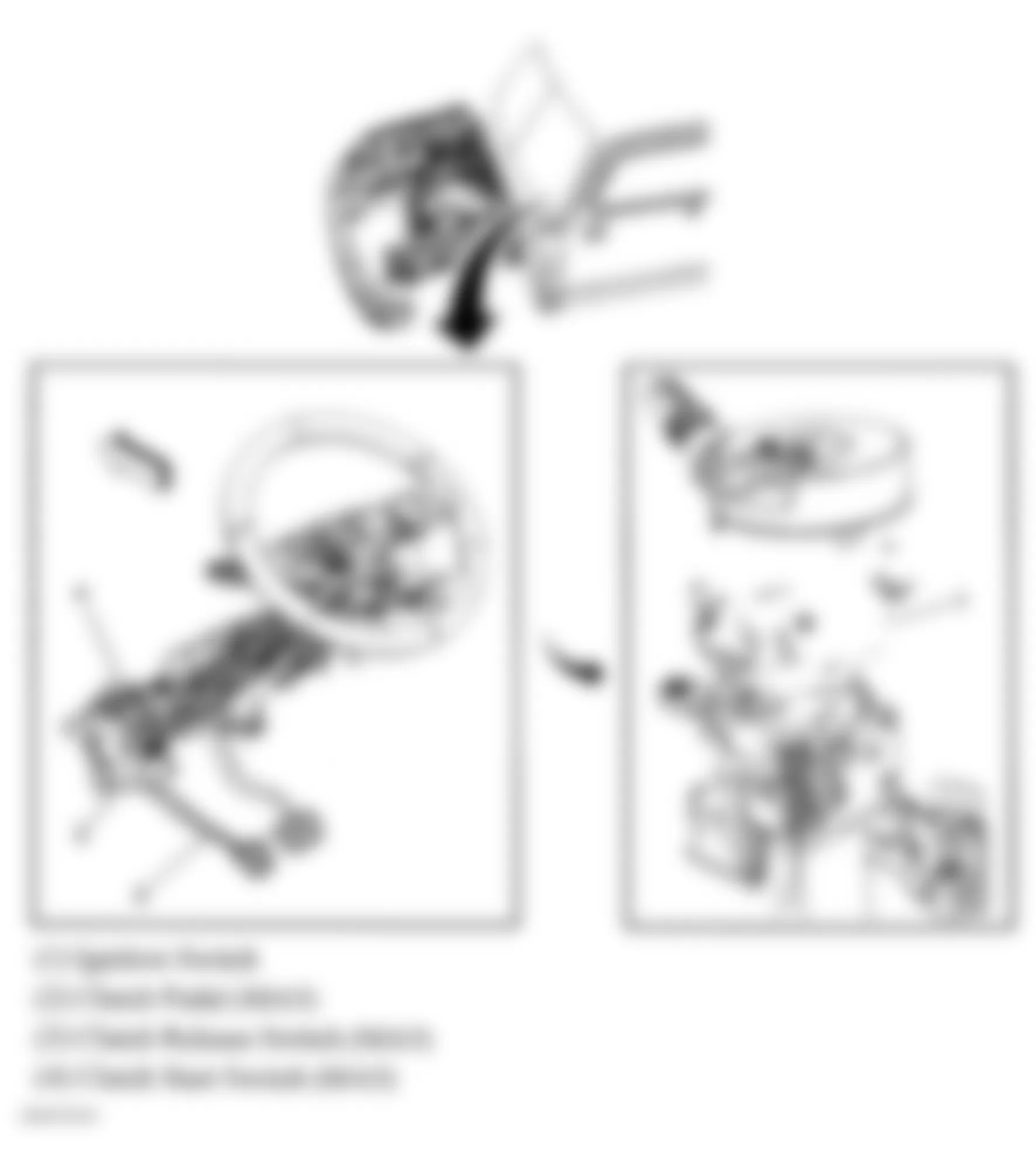
Fig. 21: Hummer H3 2007 - Component Locations - Left Rear Of Cargo Area
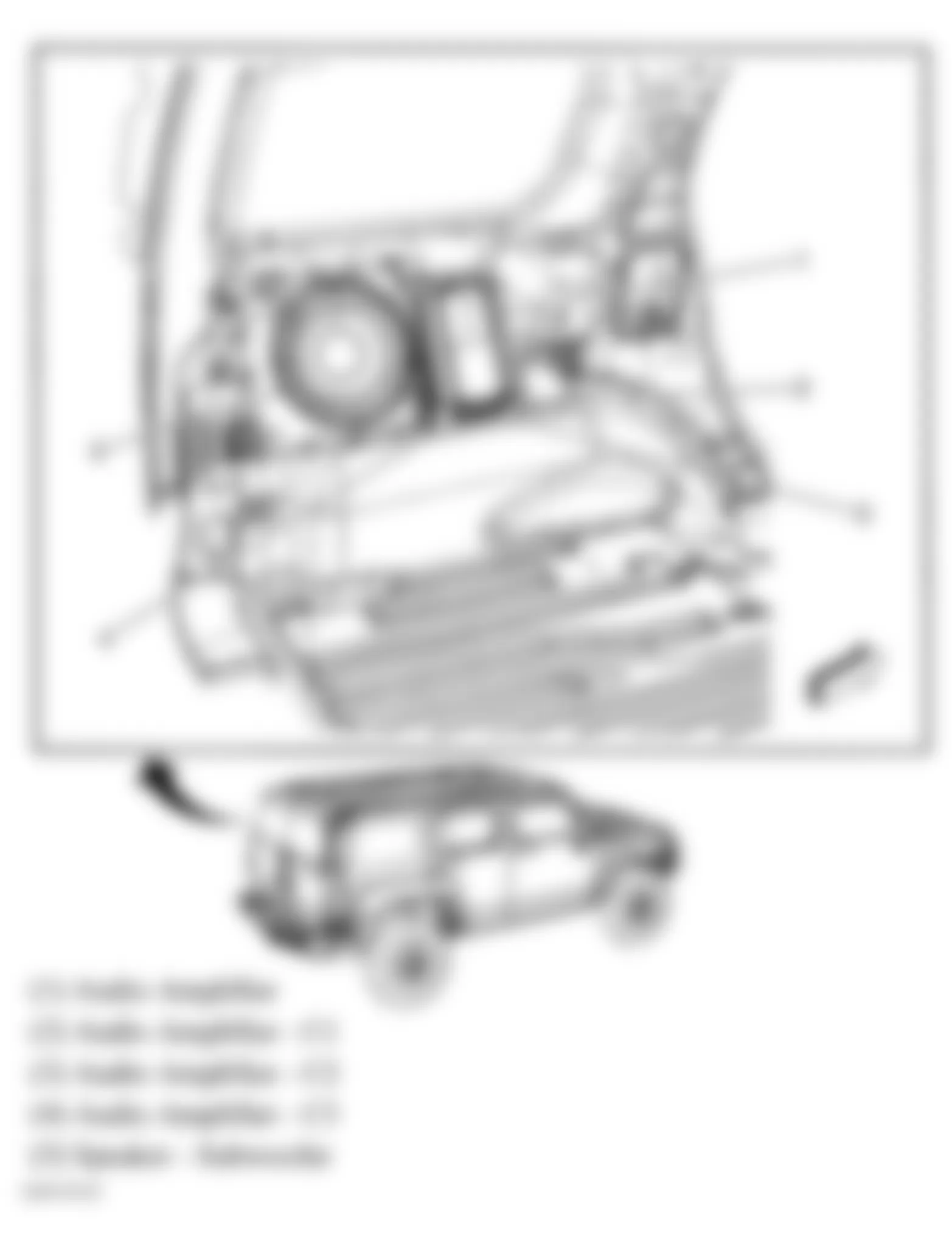
Fig. 22: Hummer H3 2007 - Component Locations - Sunroof Component Views
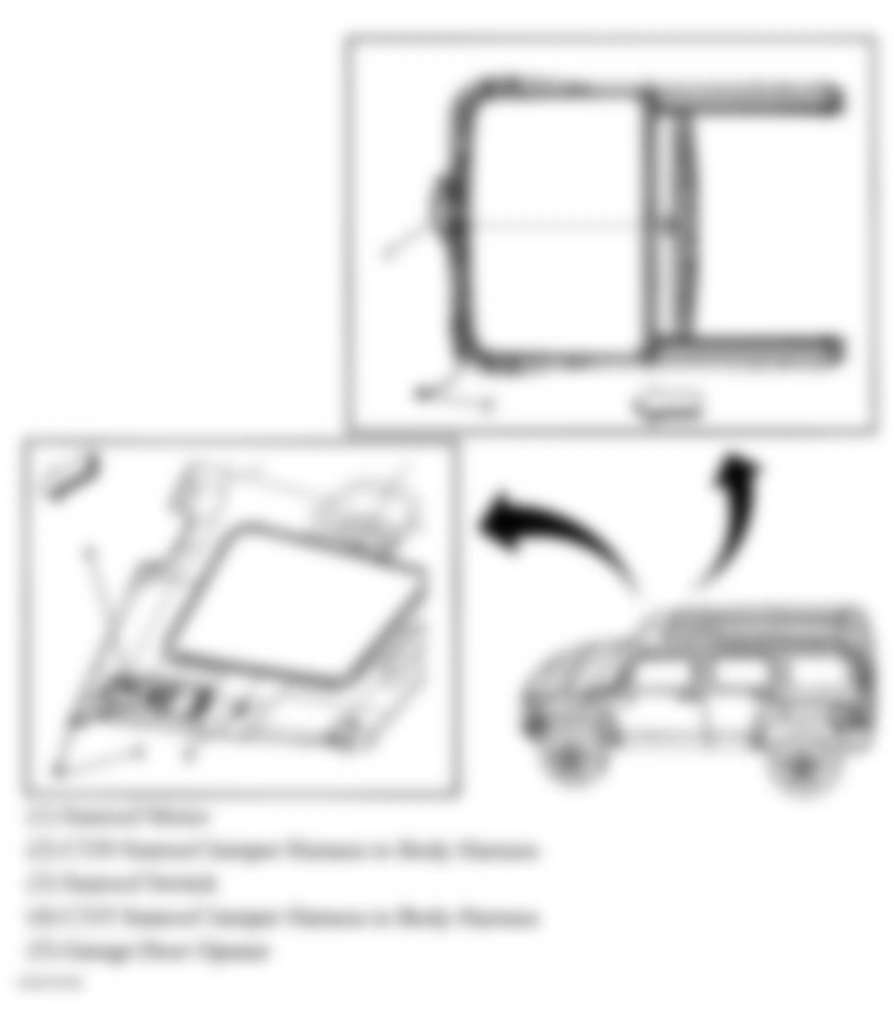
Fig. 23: Hummer H3 2007 - Component Locations - Engine Compartment
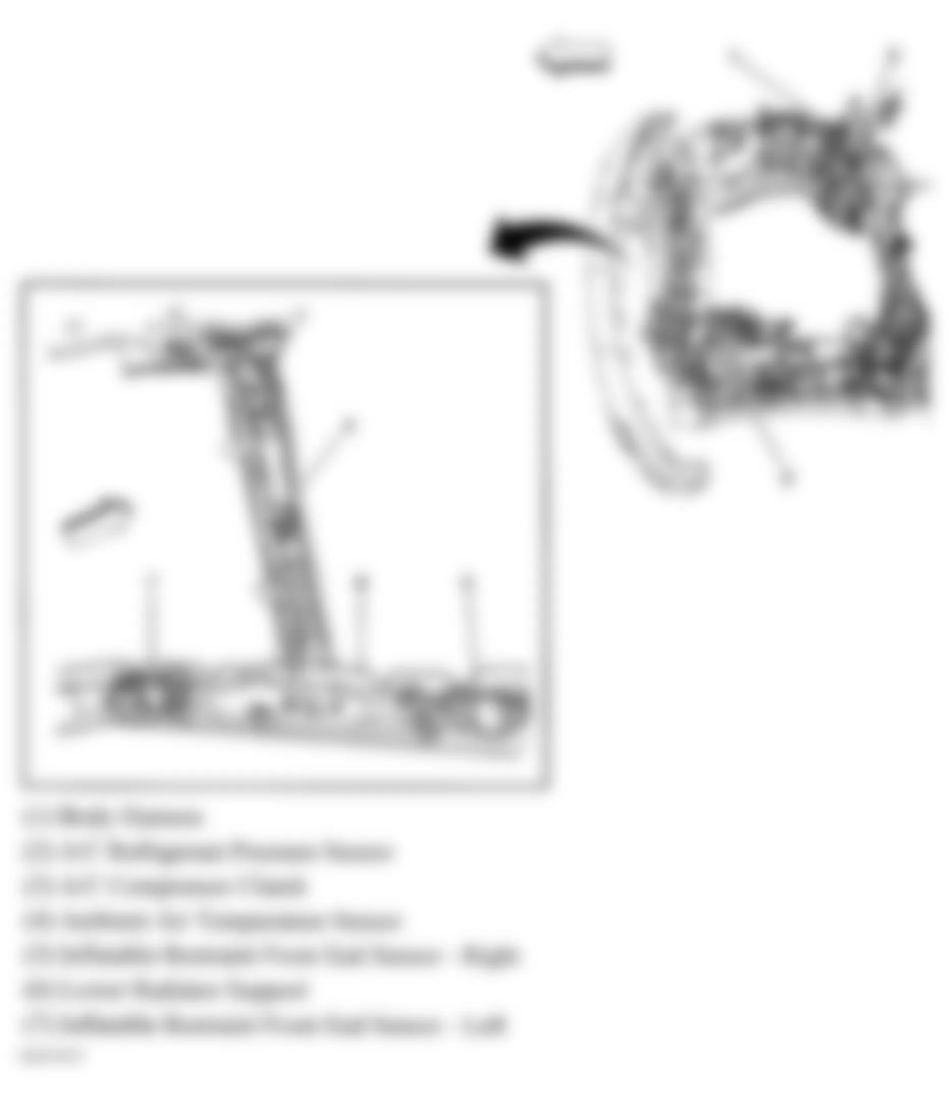
Fig. 24: Hummer H3 2007 - Component Locations - HVAC Components
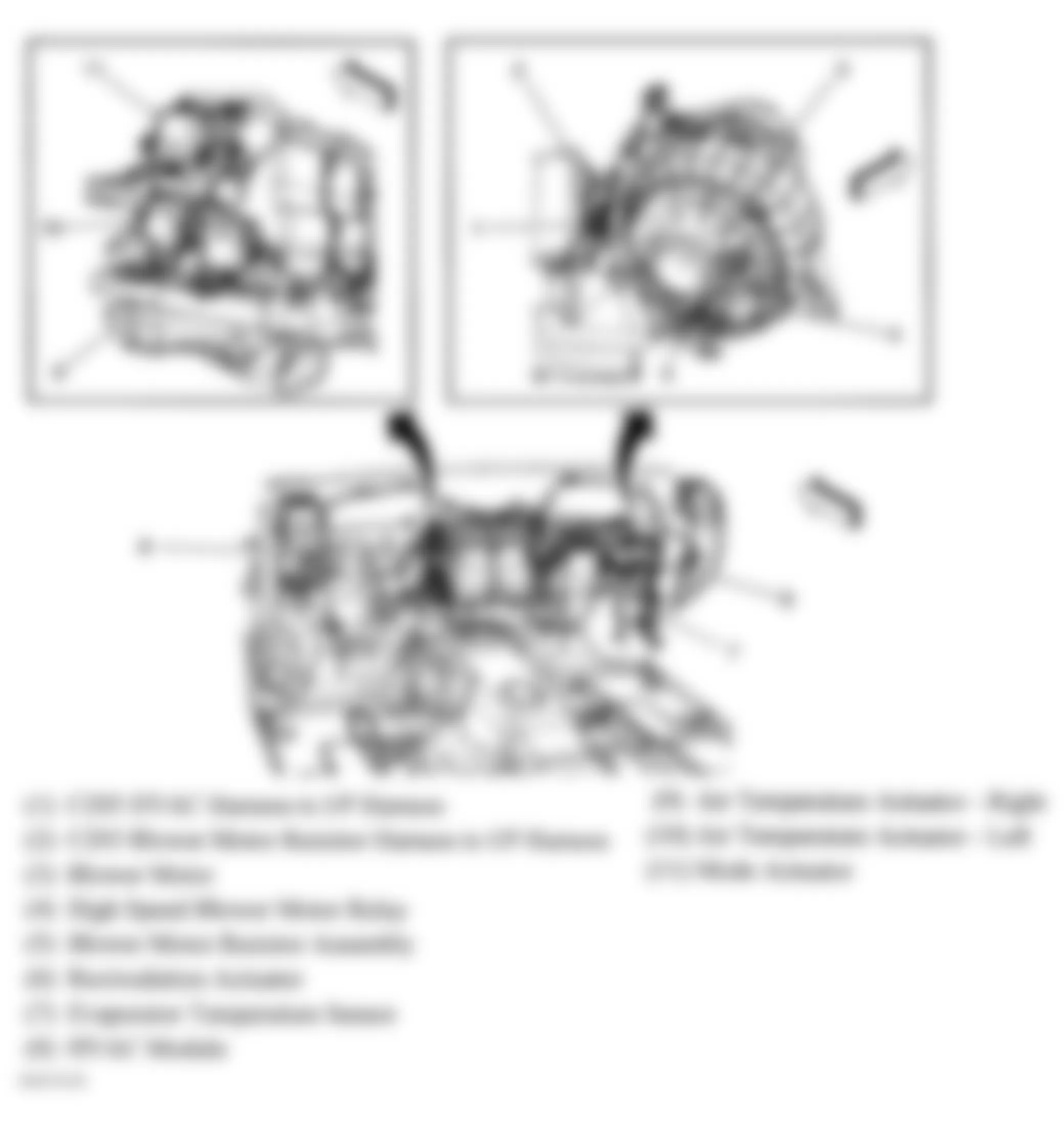
Fig. 25: Hummer H3 2007 - Component Locations - Forward Lamp Harness
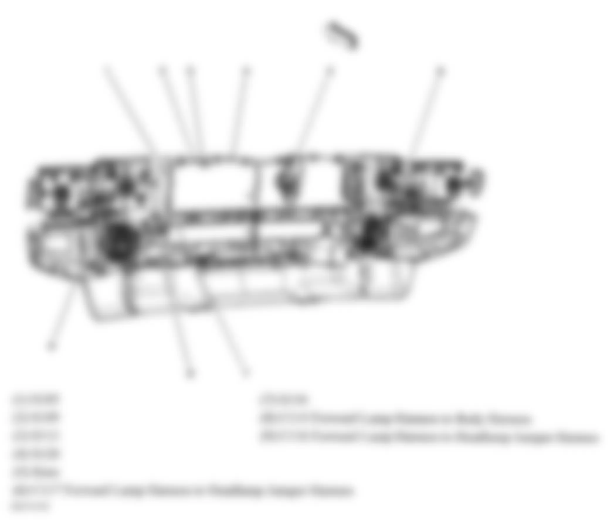
Fig. 26: Hummer H3 2007 - Component Locations - Dash Harness
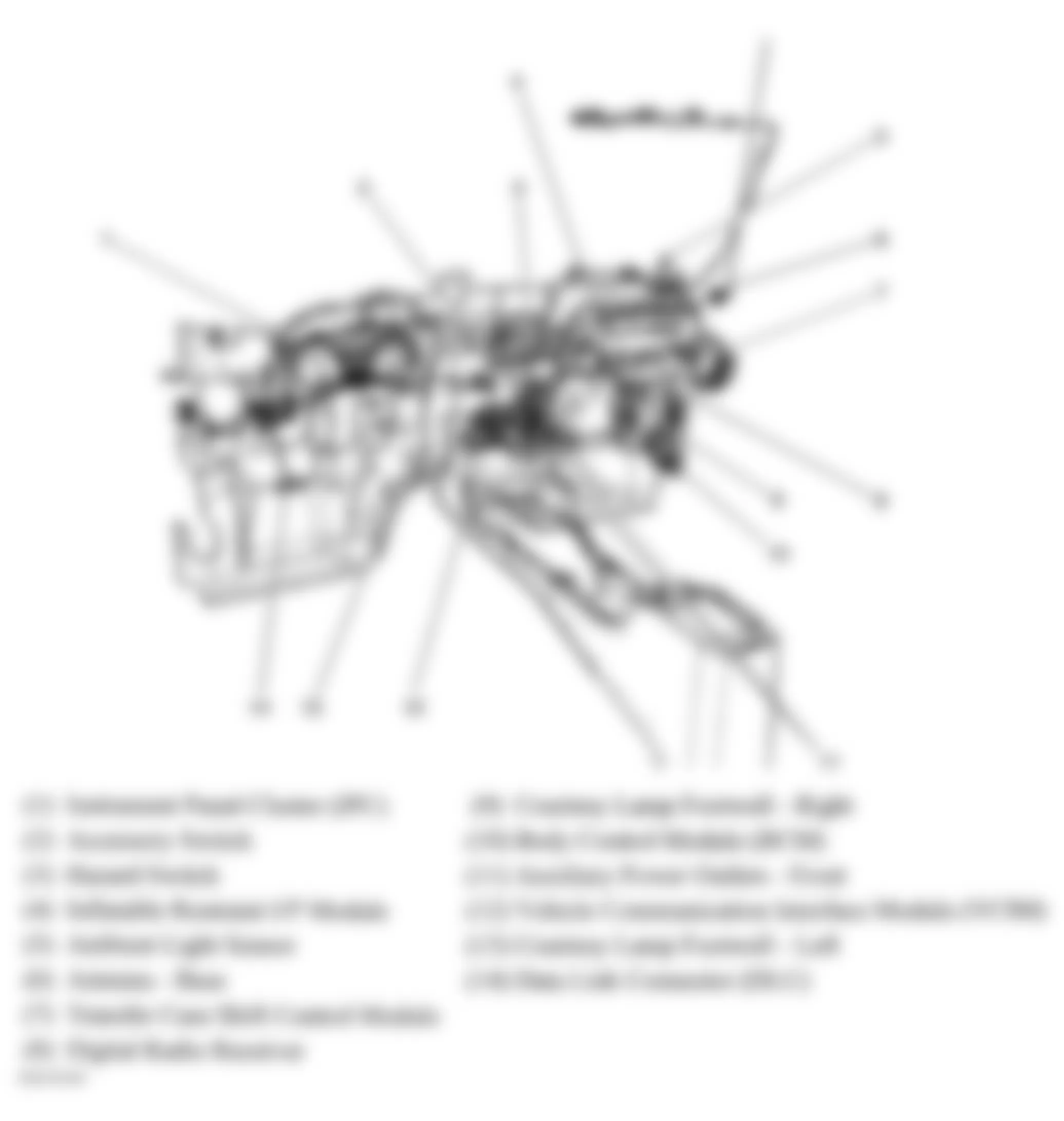
Fig. 27: Hummer H3 2007 - Component Locations - Vehicle Overview
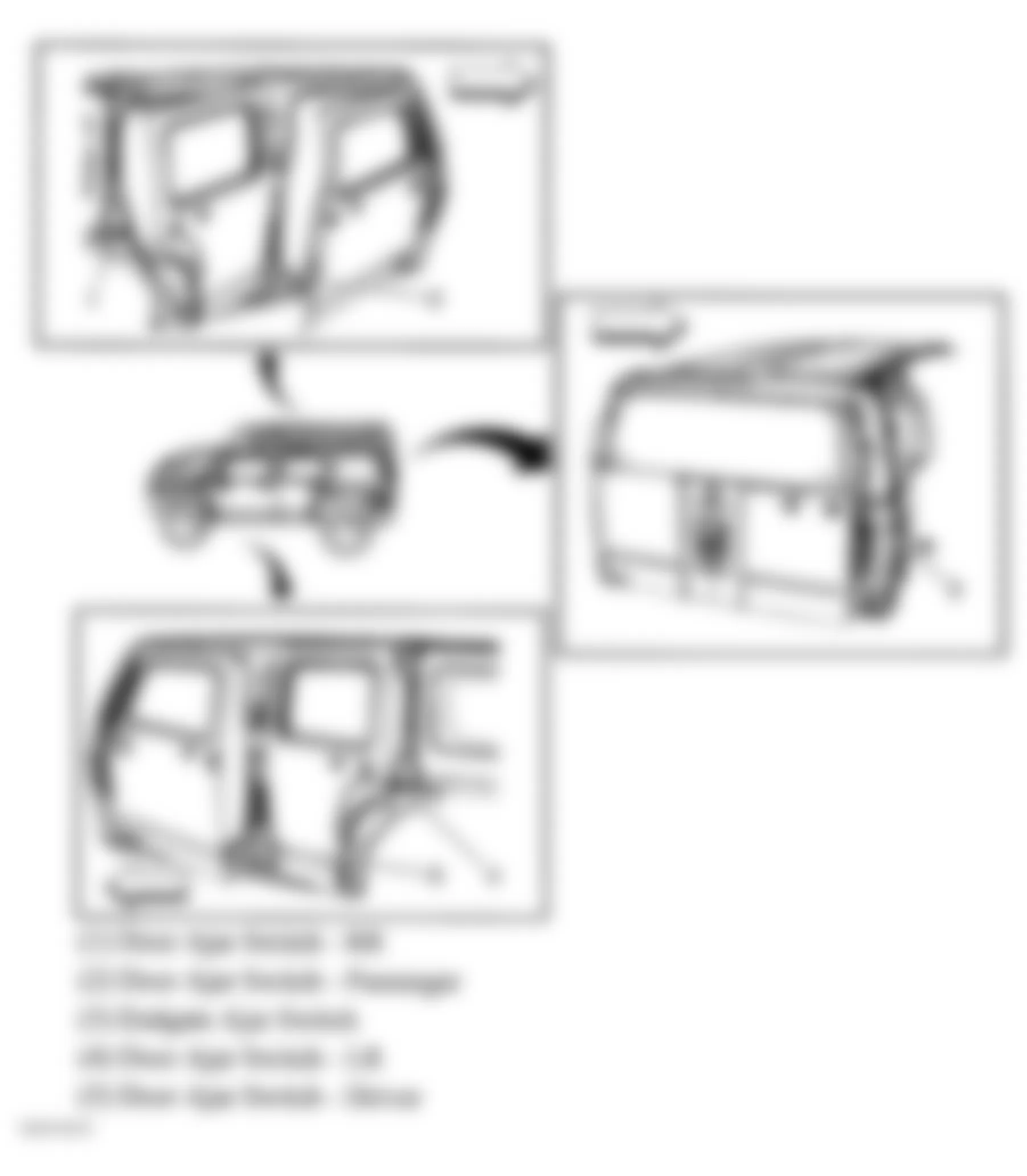
Fig. 28: Hummer H3 2007 - Component Locations - Transmission Assembly
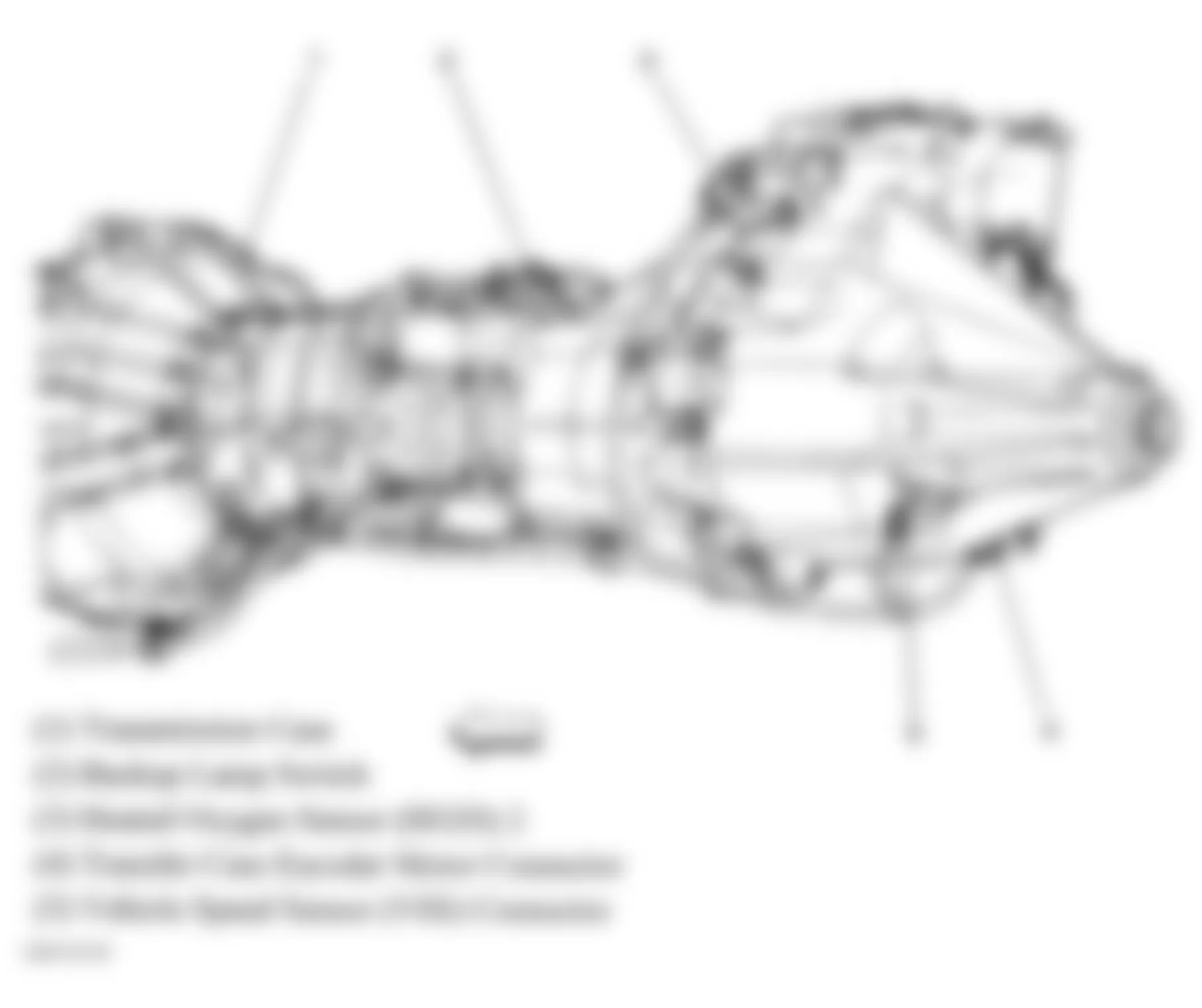
Fig. 29: Hummer H3 2007 - Component Locations - Steering Column
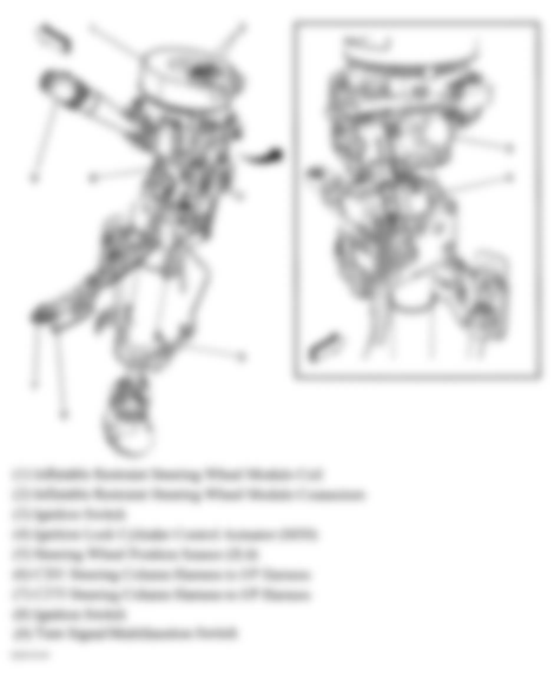
Fig. 30: Hummer H3 2007 - Component Locations - Side Impact Sensor (SIR) Components
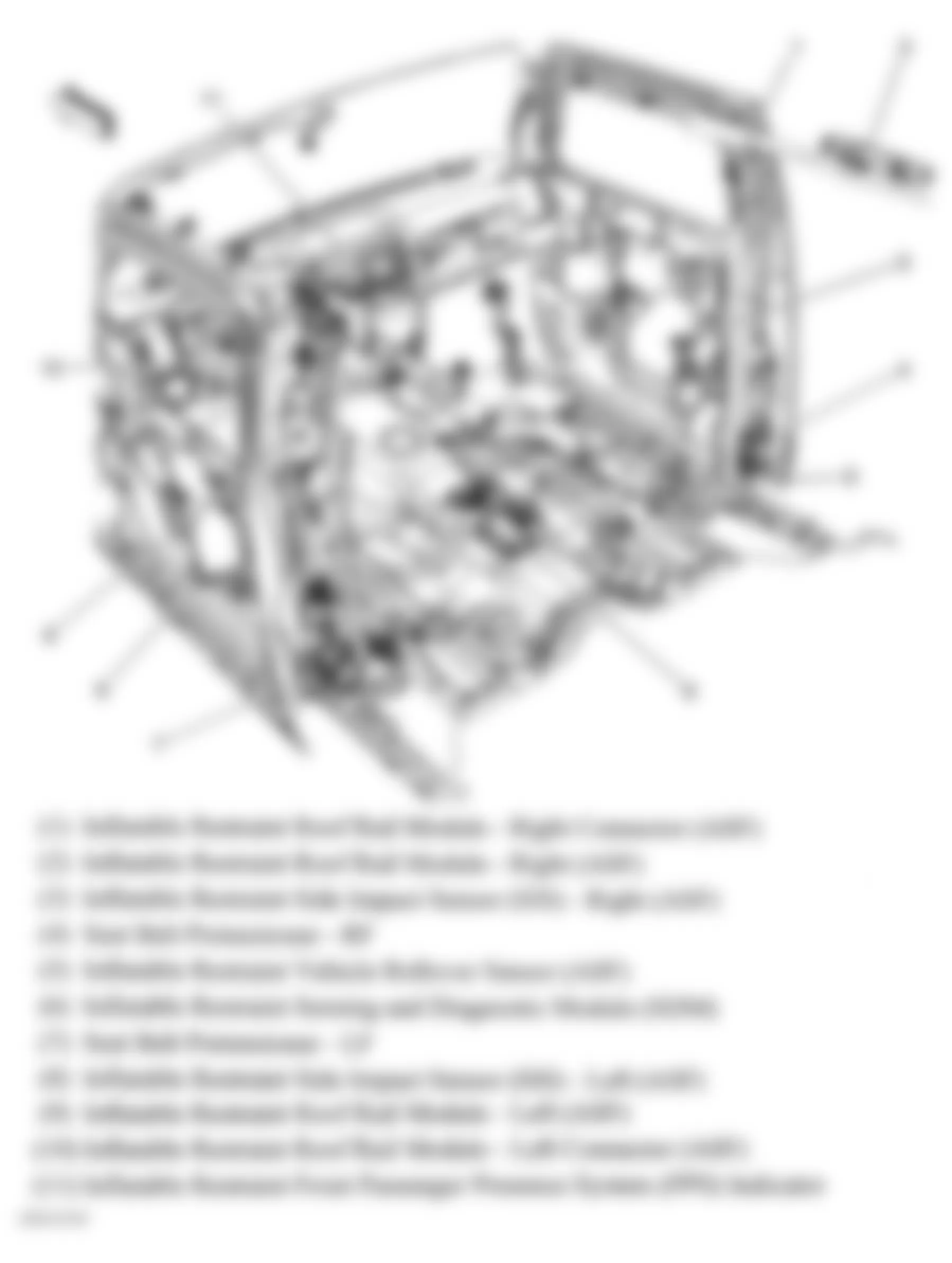
Fig. 31: Hummer H3 2007 - Component Locations - Floor Pan
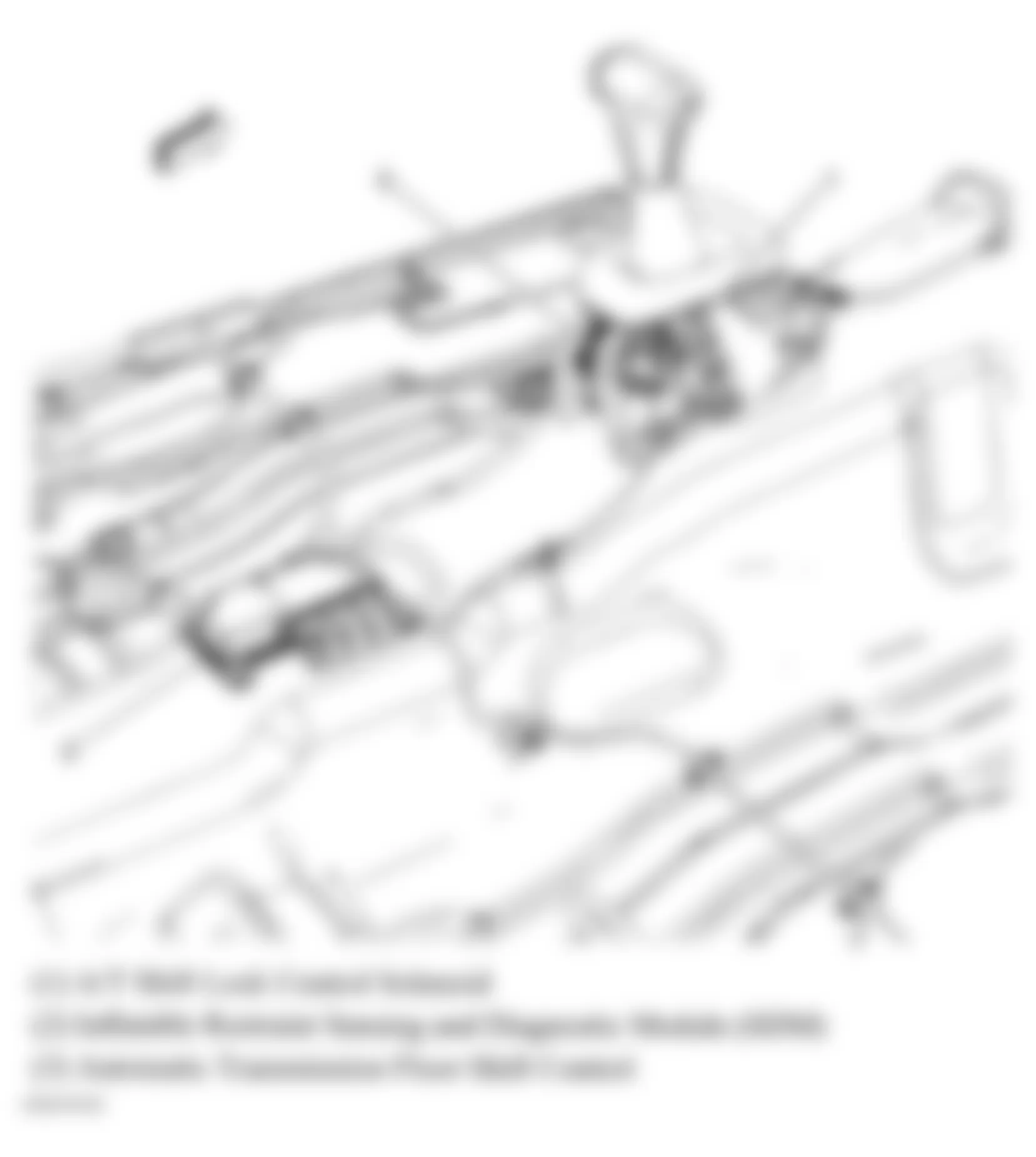
Fig. 32: Hummer H3 2007 - Component Locations - Tire Assembly
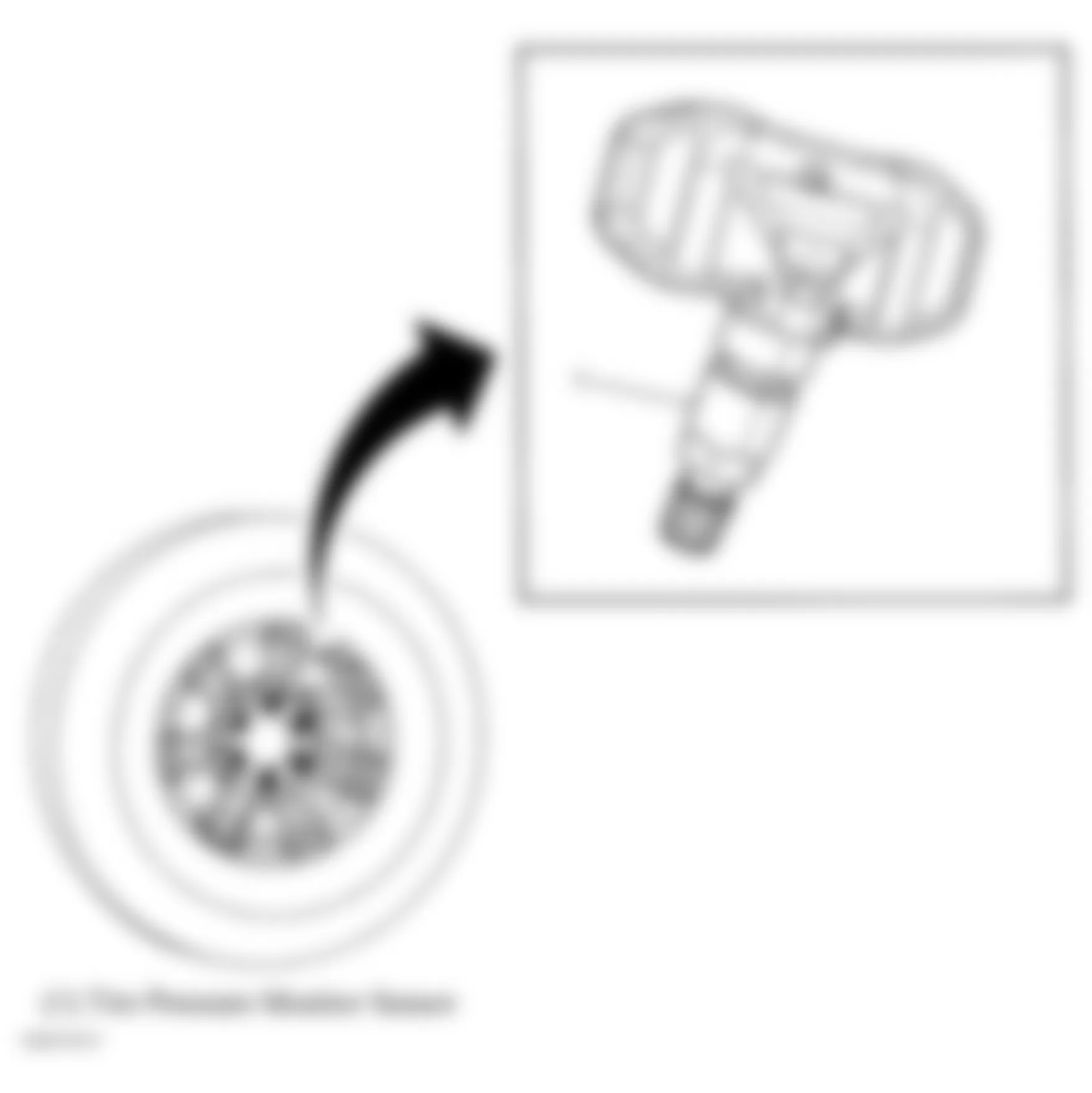
Fig. 33: Hummer H3 2007 - Component Locations - Right Side Of Dash
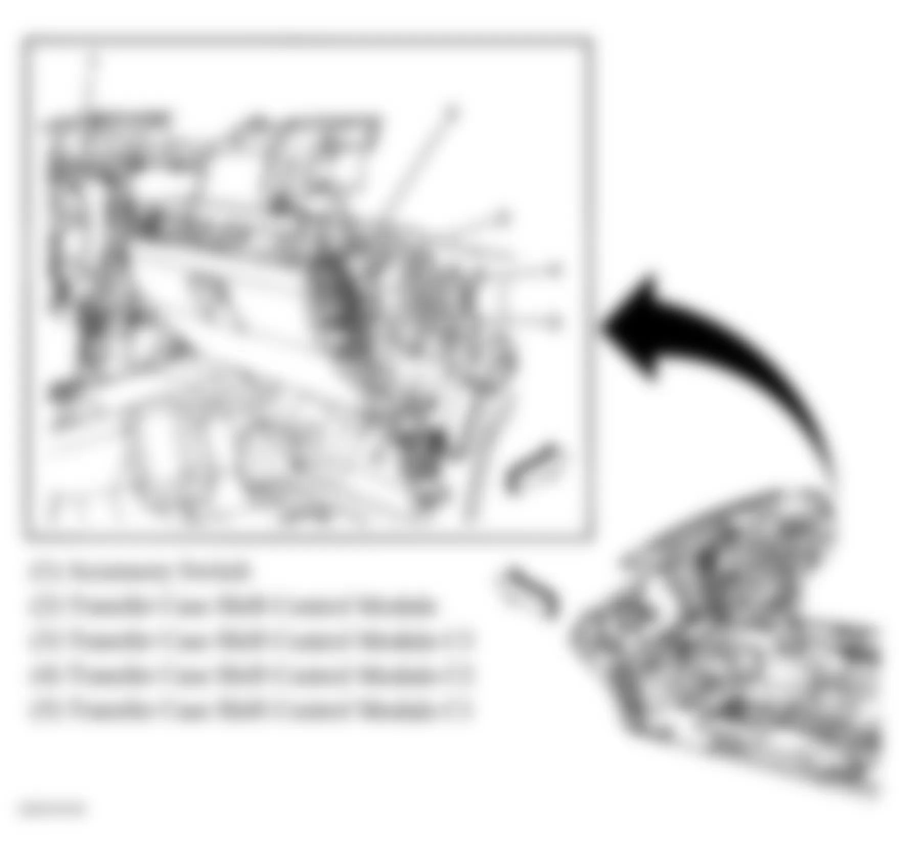
Fig. 34: Hummer H3 2007 - Component Locations - Engine Compartment
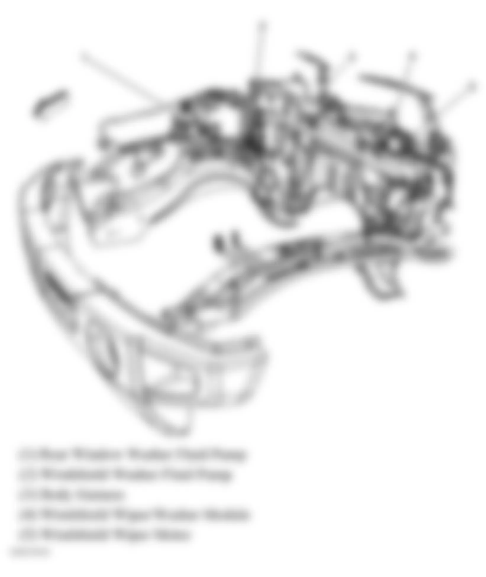
Fig. 35: Hummer H3 2007 - Component Locations - Vehicle Overview
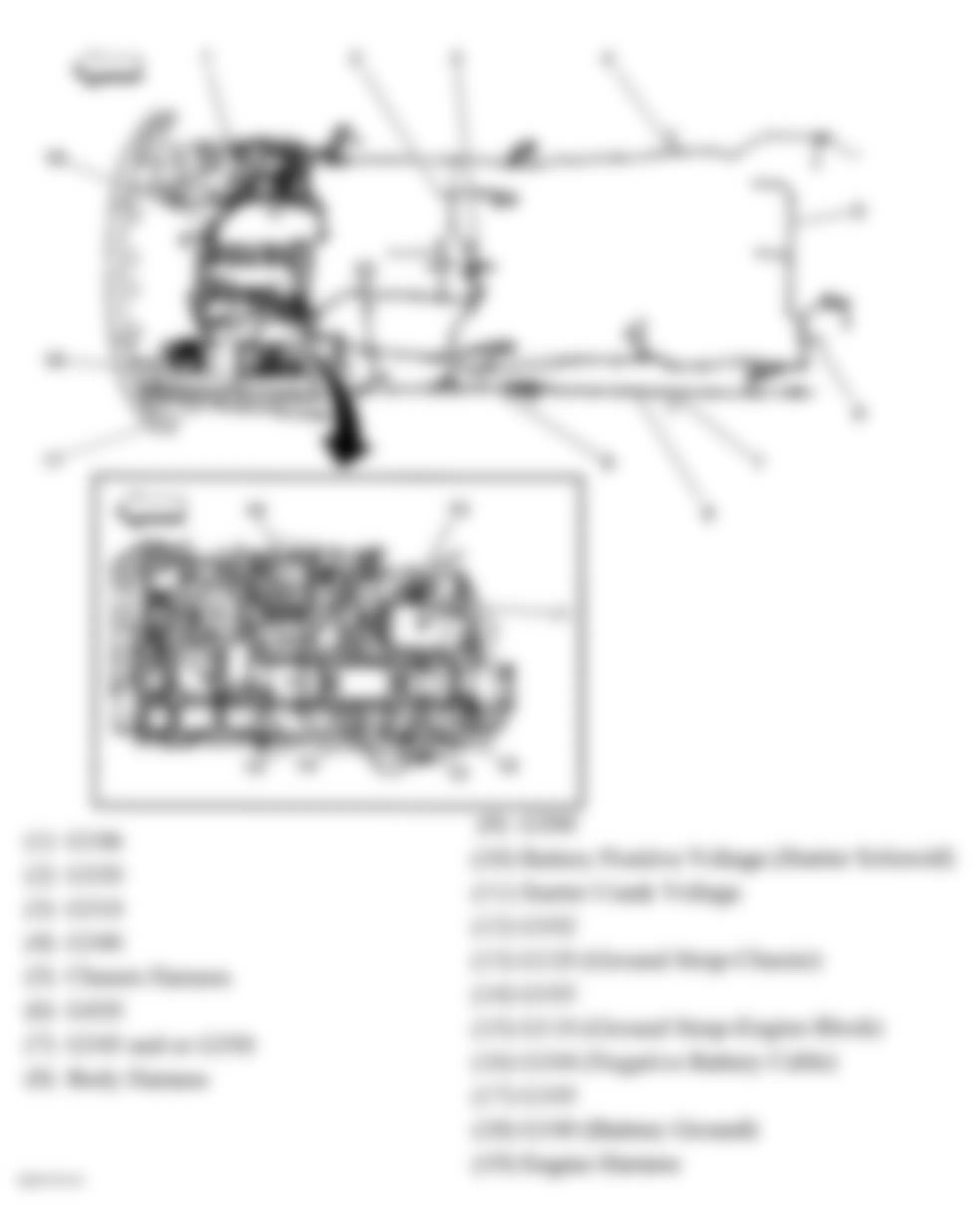
Fig. 36: Hummer H3 2007 - Component Locations - Dash Harness
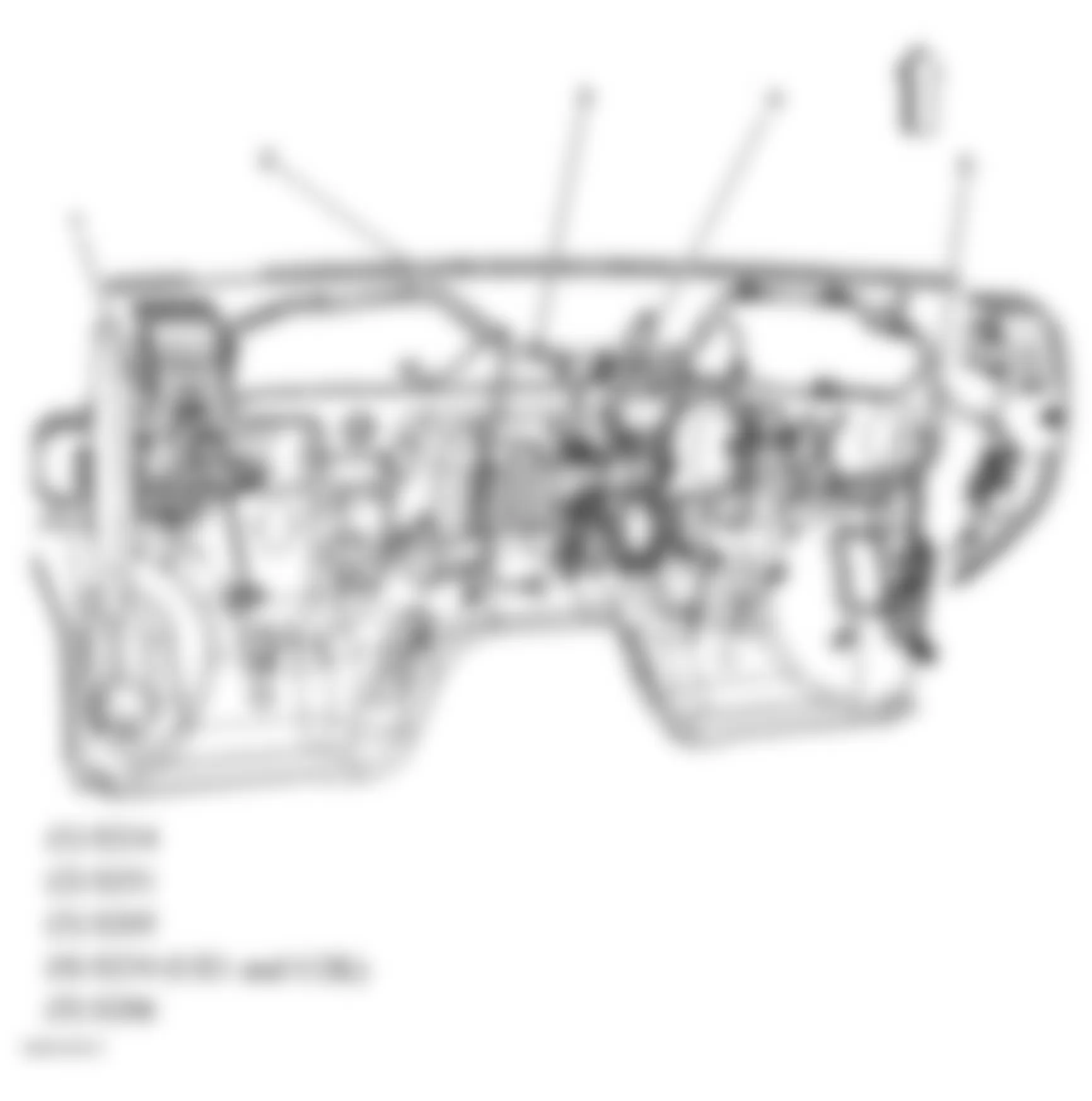
Fig. 37: Hummer H3 2007 - Component Locations - HVAC Module Harness
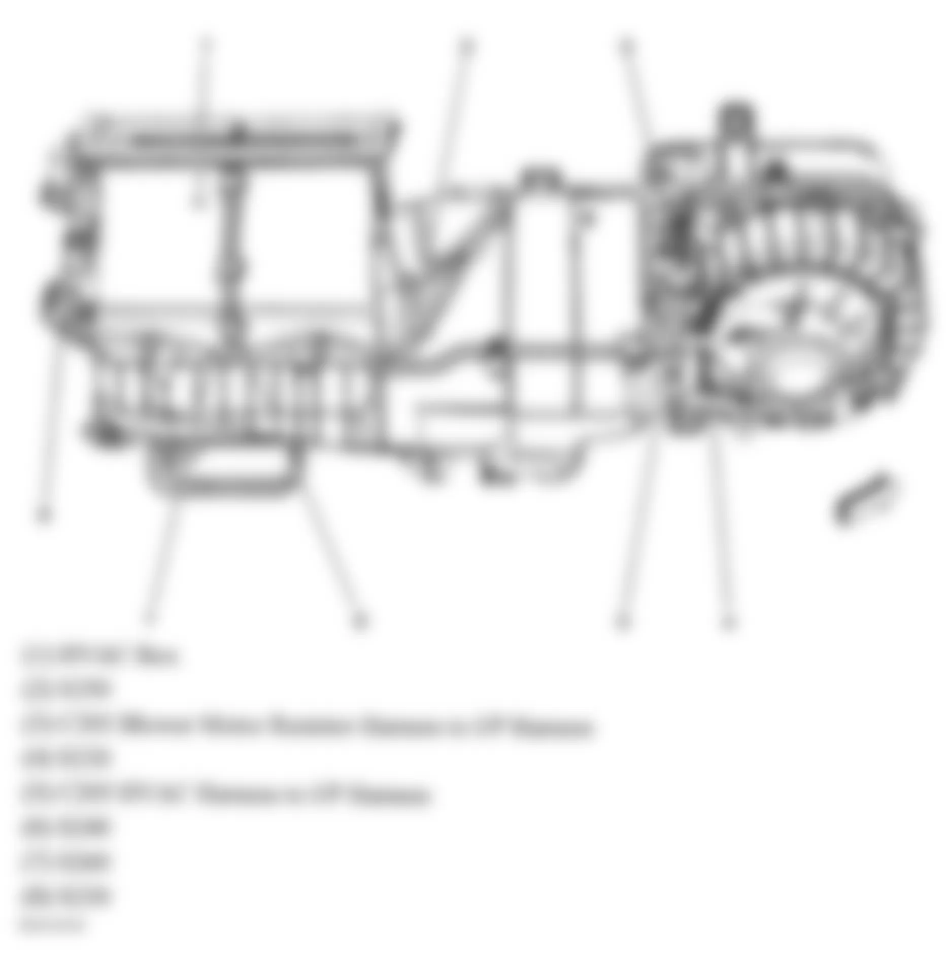
Fig. 38: Hummer H3 2007 - Component Locations - Body Harness (Front)
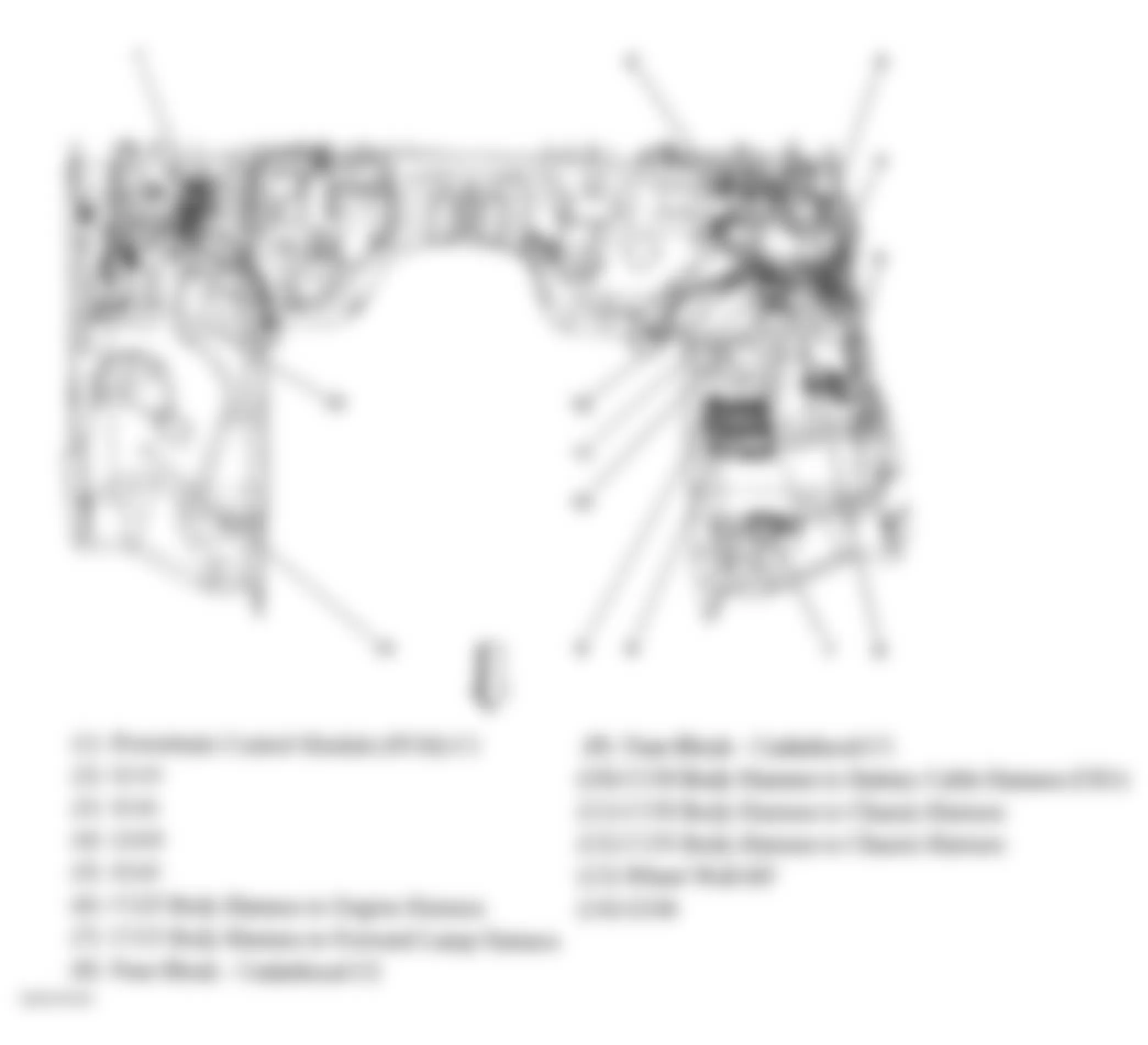
Fig. 39: Hummer H3 2007 - Component Locations - Headliner
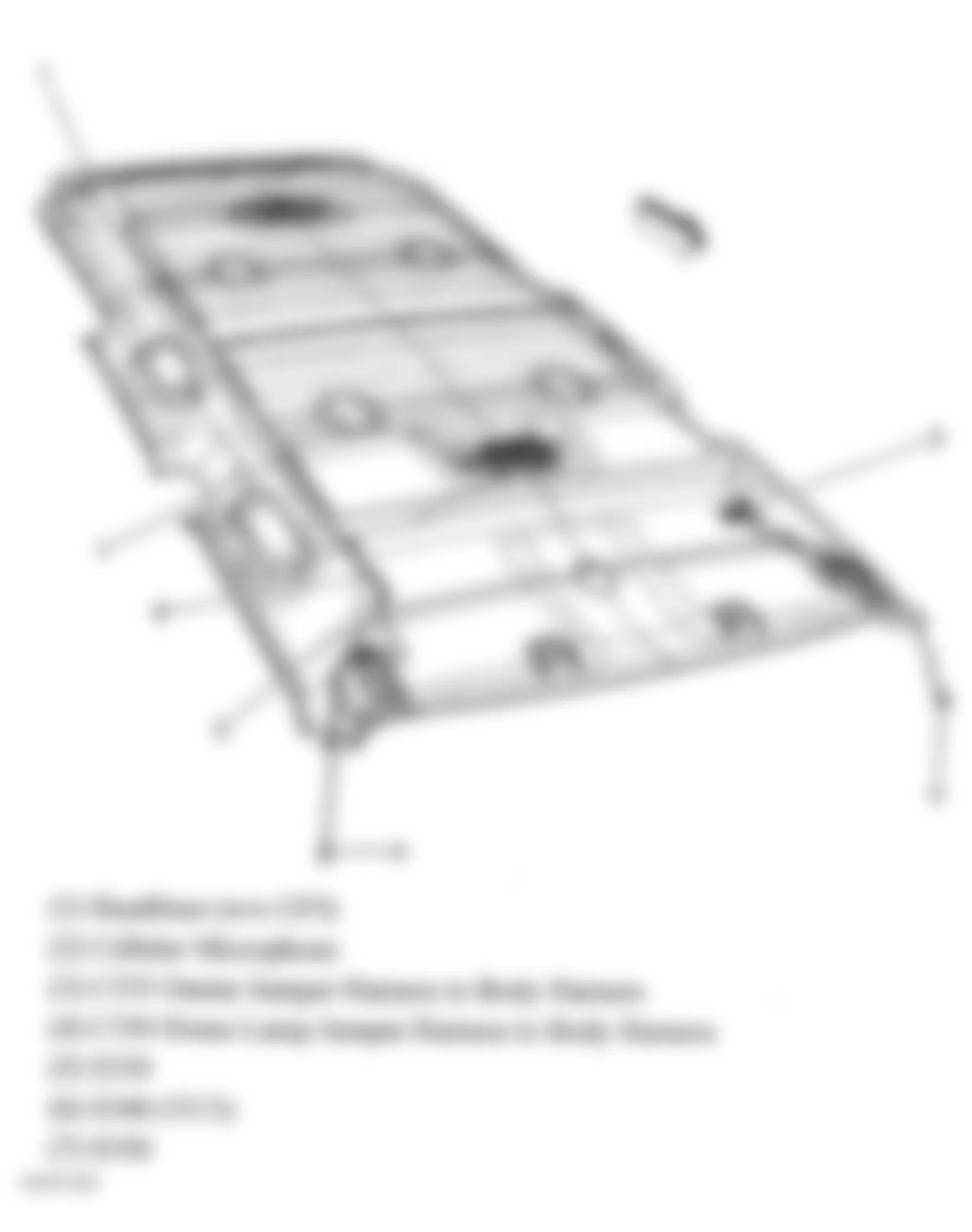
Fig. 40: Hummer H3 2007 - Component Locations - Driver Door
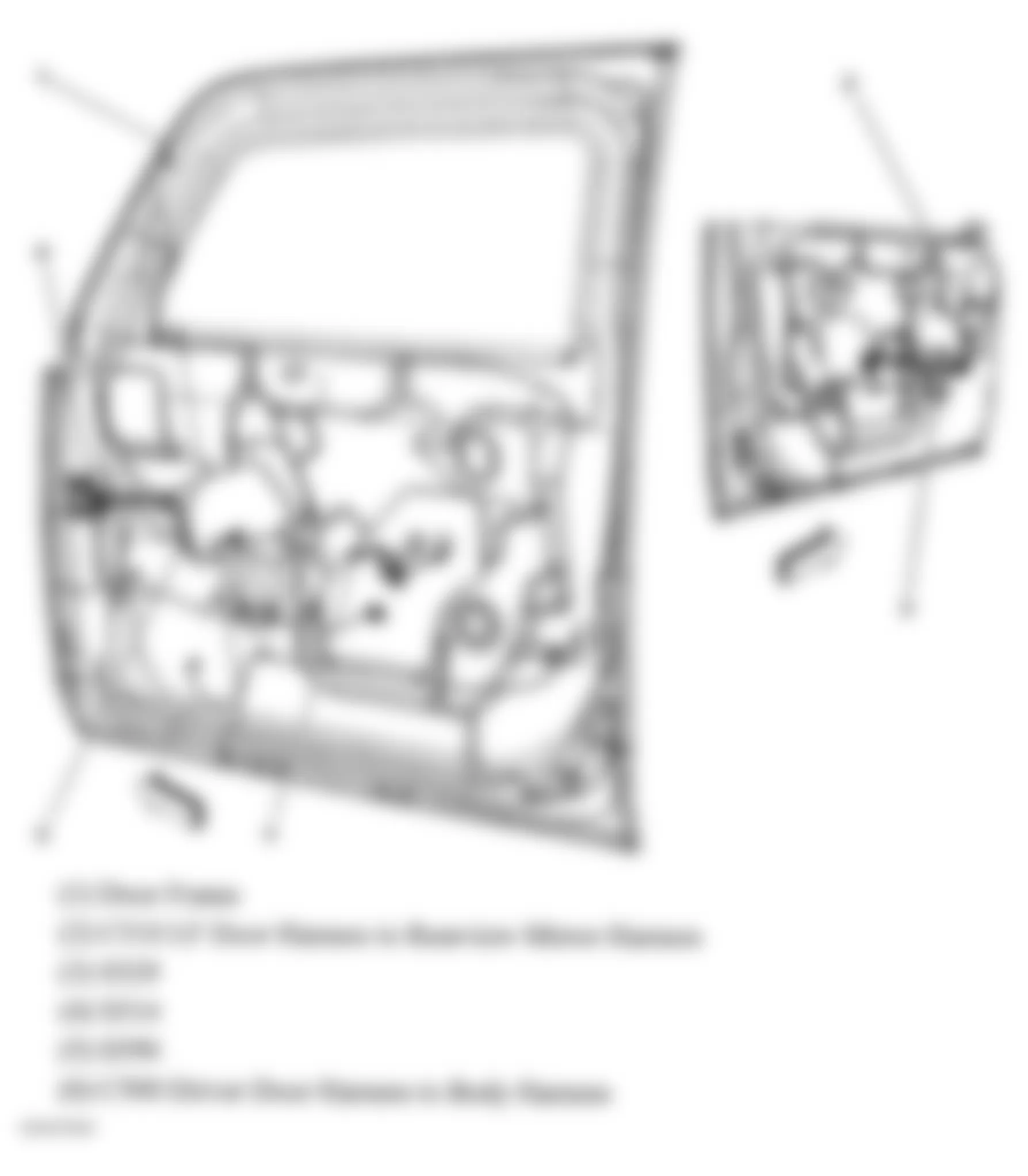
Fig. 41: Hummer H3 2007 - Component Locations - Endgate
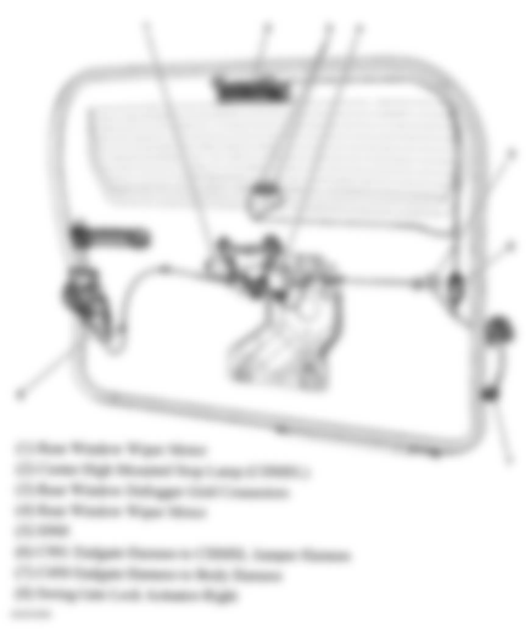
Fig. 42: Hummer H3 2007 - Component Locations - Engine Electrical Components
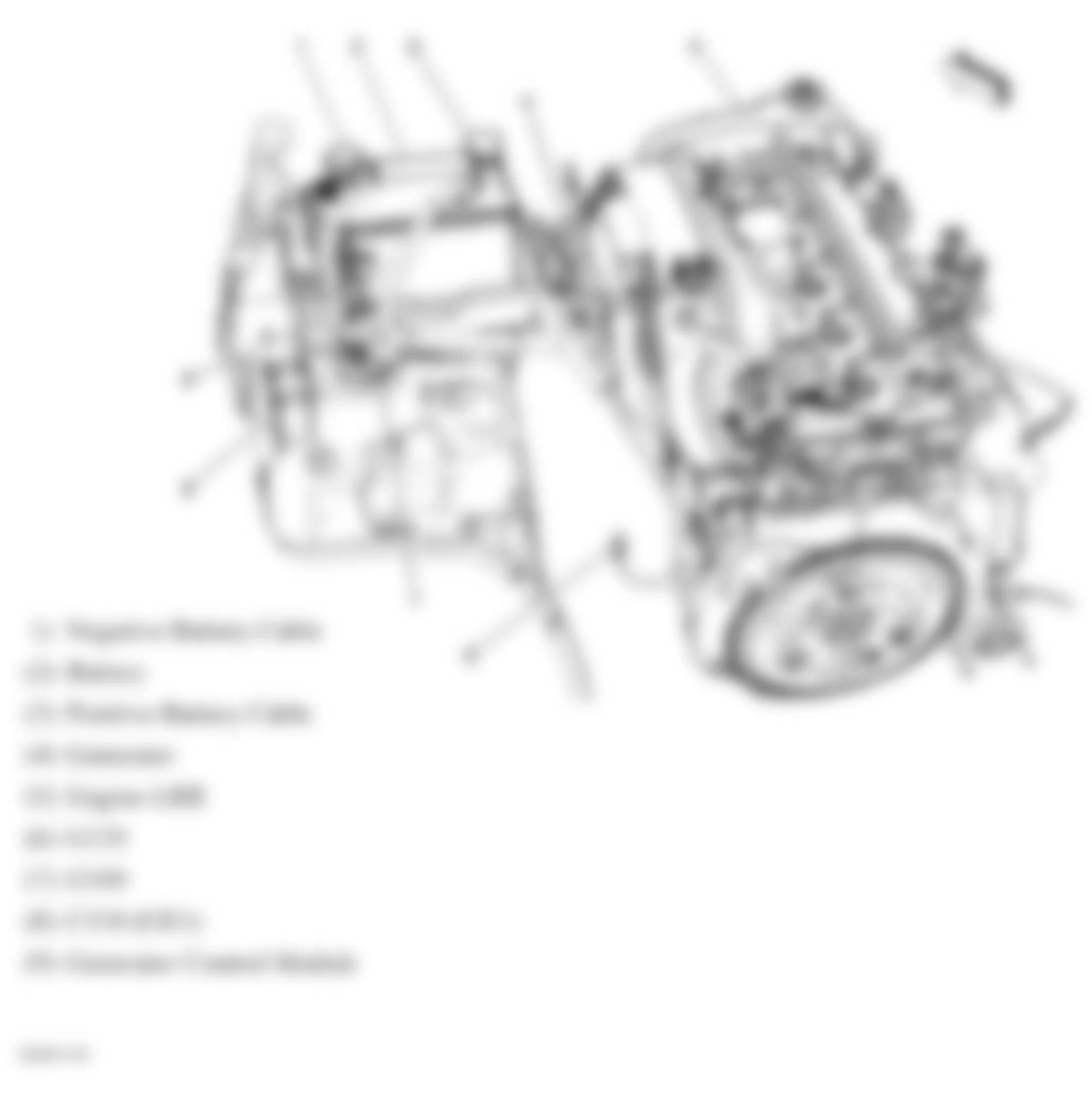
Fig. 43: Hummer H3 2007 - Component Locations - Right Rear Door (Crew Cab)
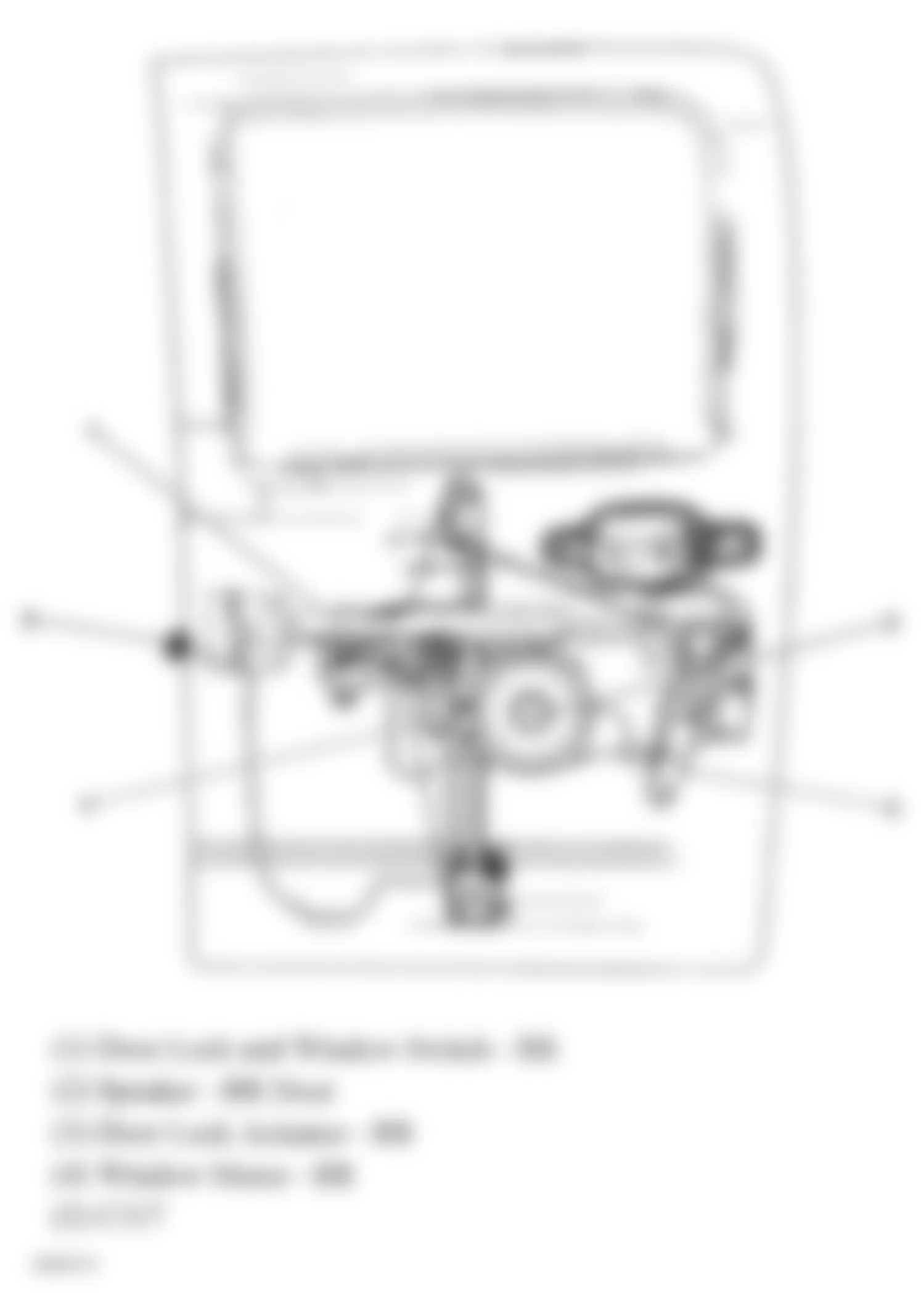
Fig. 44: Hummer H3 2007 - Component Locations - Driver Seat Components
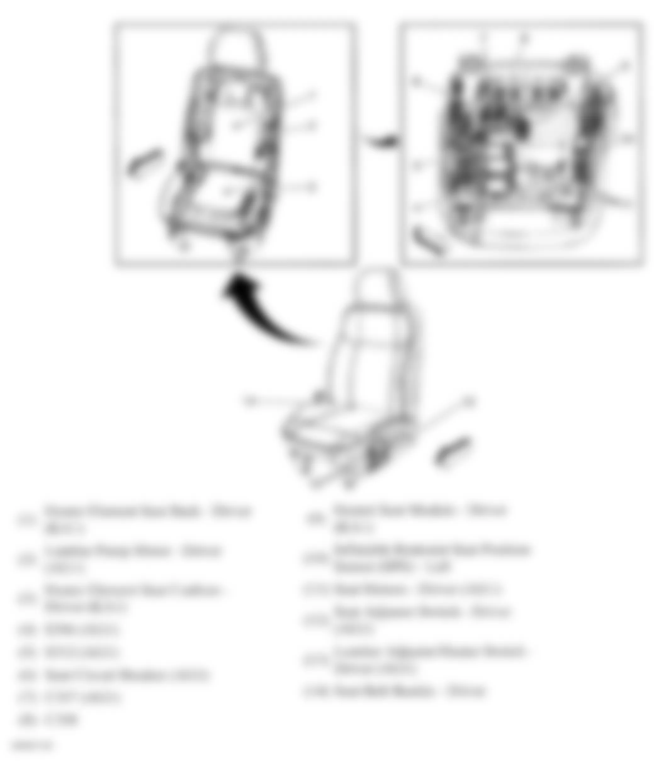
Fig. 45: Hummer H3 2007 - Component Locations - Passenger Seat Components
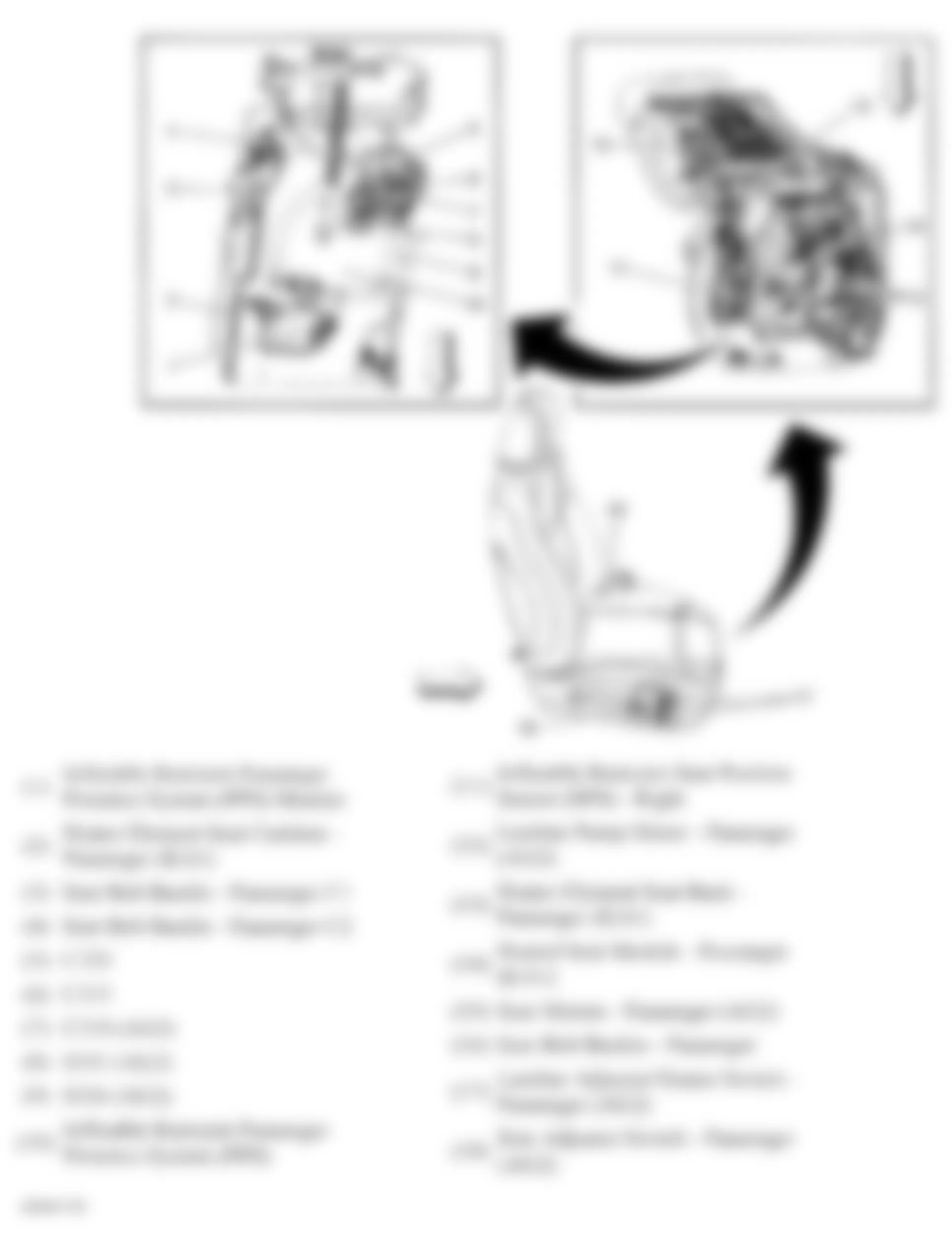
Fig. 46: Hummer H3 2007 - Component Locations - Brake Components (W/O Active Brake Control)
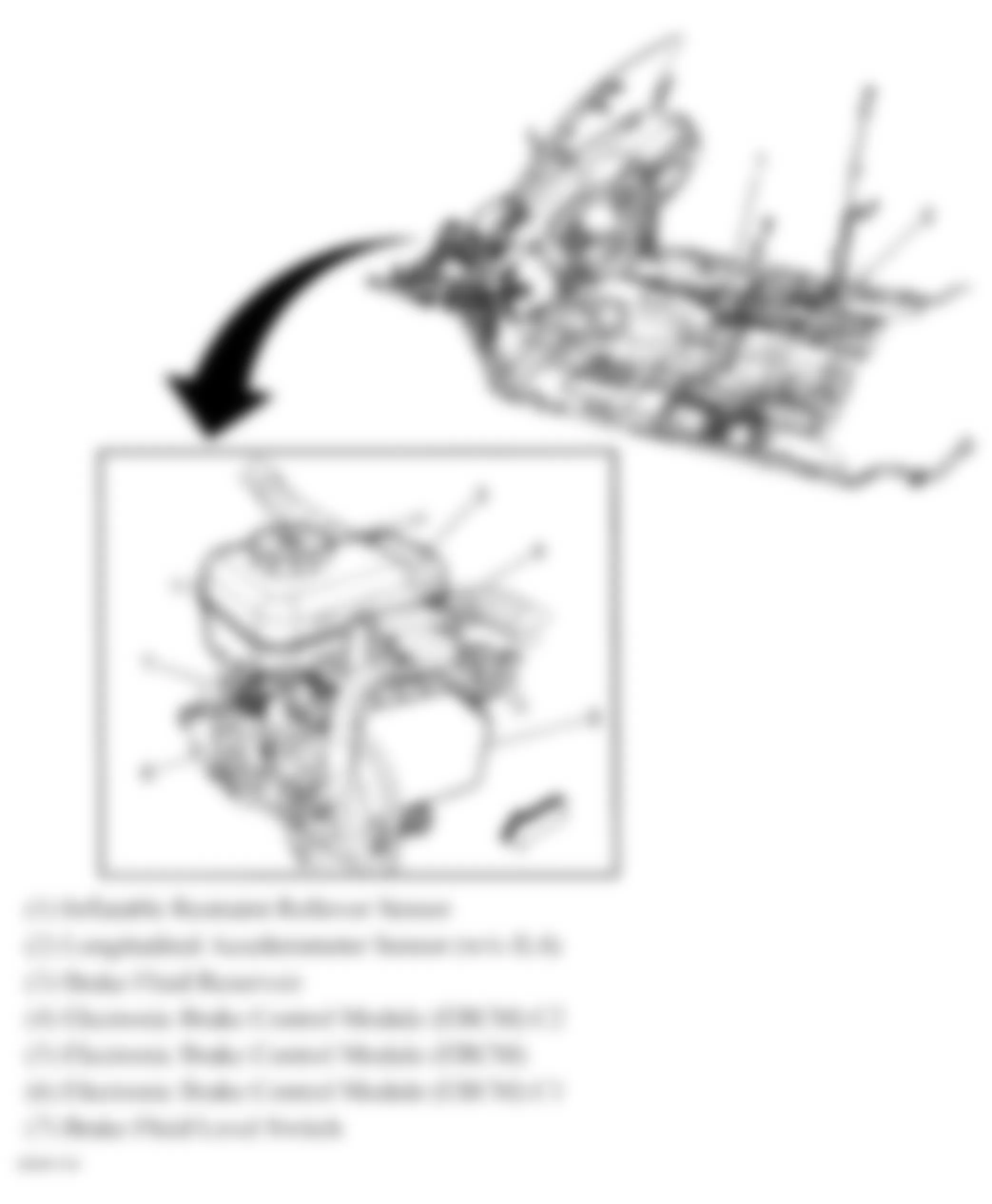
Fig. 47: Hummer H3 2007 - Component Locations - Park Neutral Position (PNP) Switch
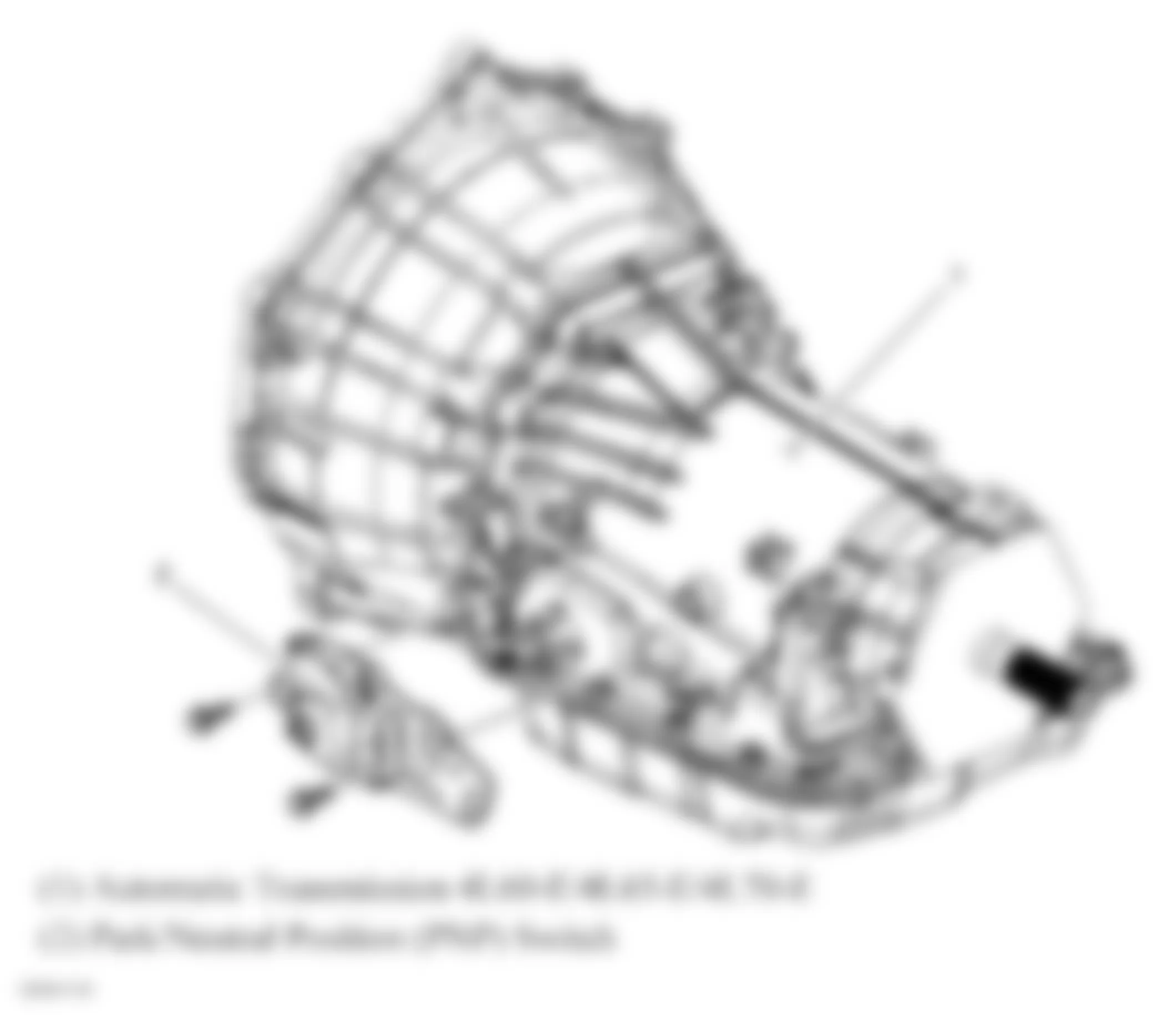
Fig. 48: Hummer H3 2007 - Component Locations - Rear Axle Components
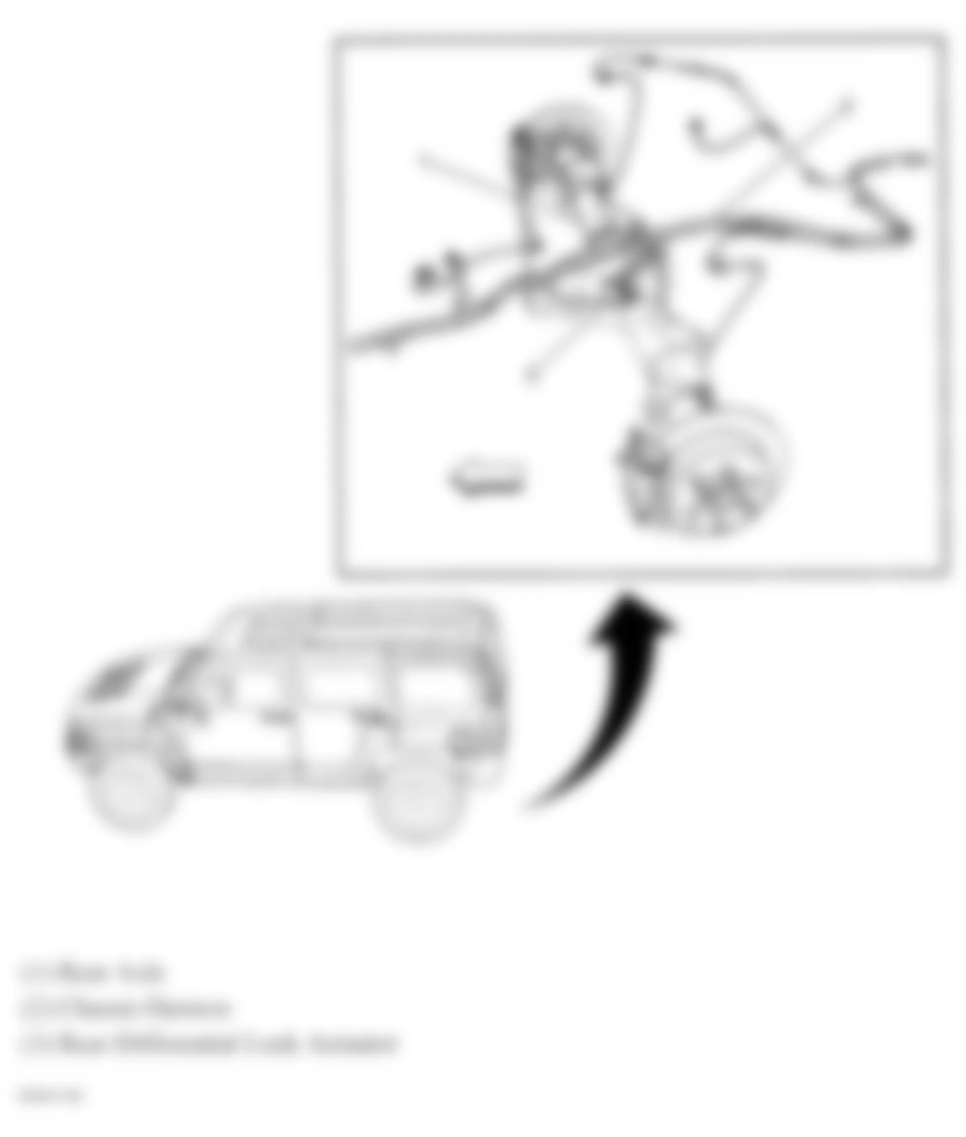
Fig. 49: Hummer H3 2007 - Component Locations - Rear Exterior Lights
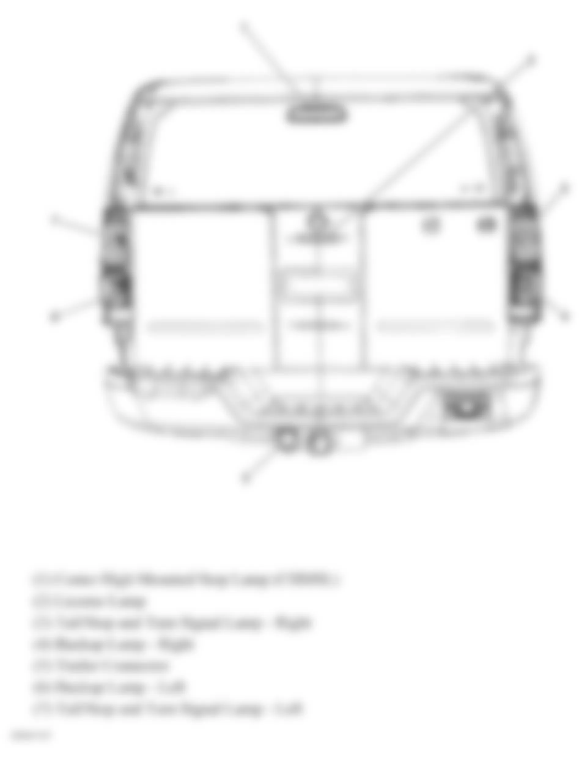
Fig. 50: Hummer H3 2007 - Component Locations - Right Engine Harness
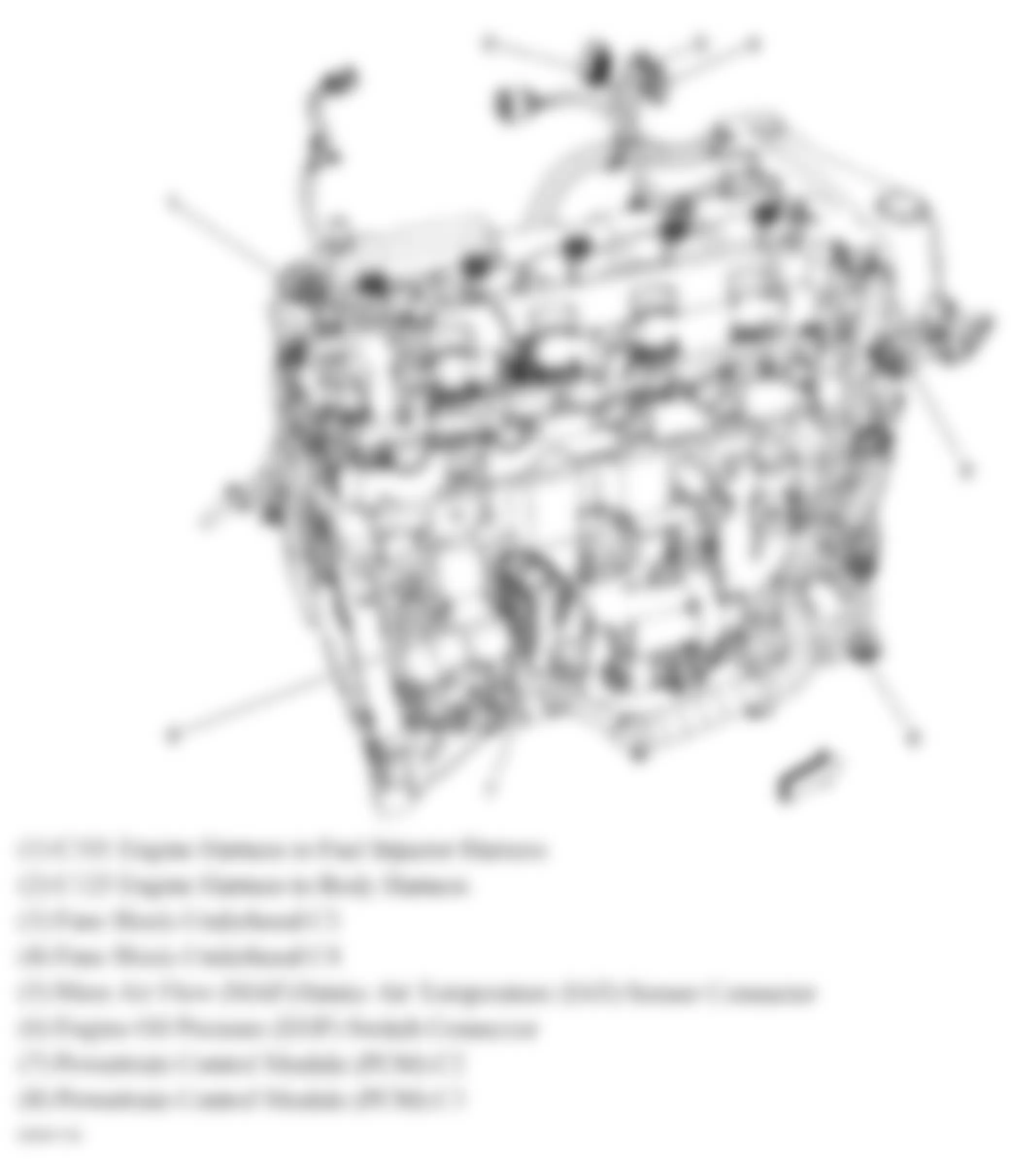
Fig. 51: Hummer H3 2007 - Component Locations - Left Side Of Dash
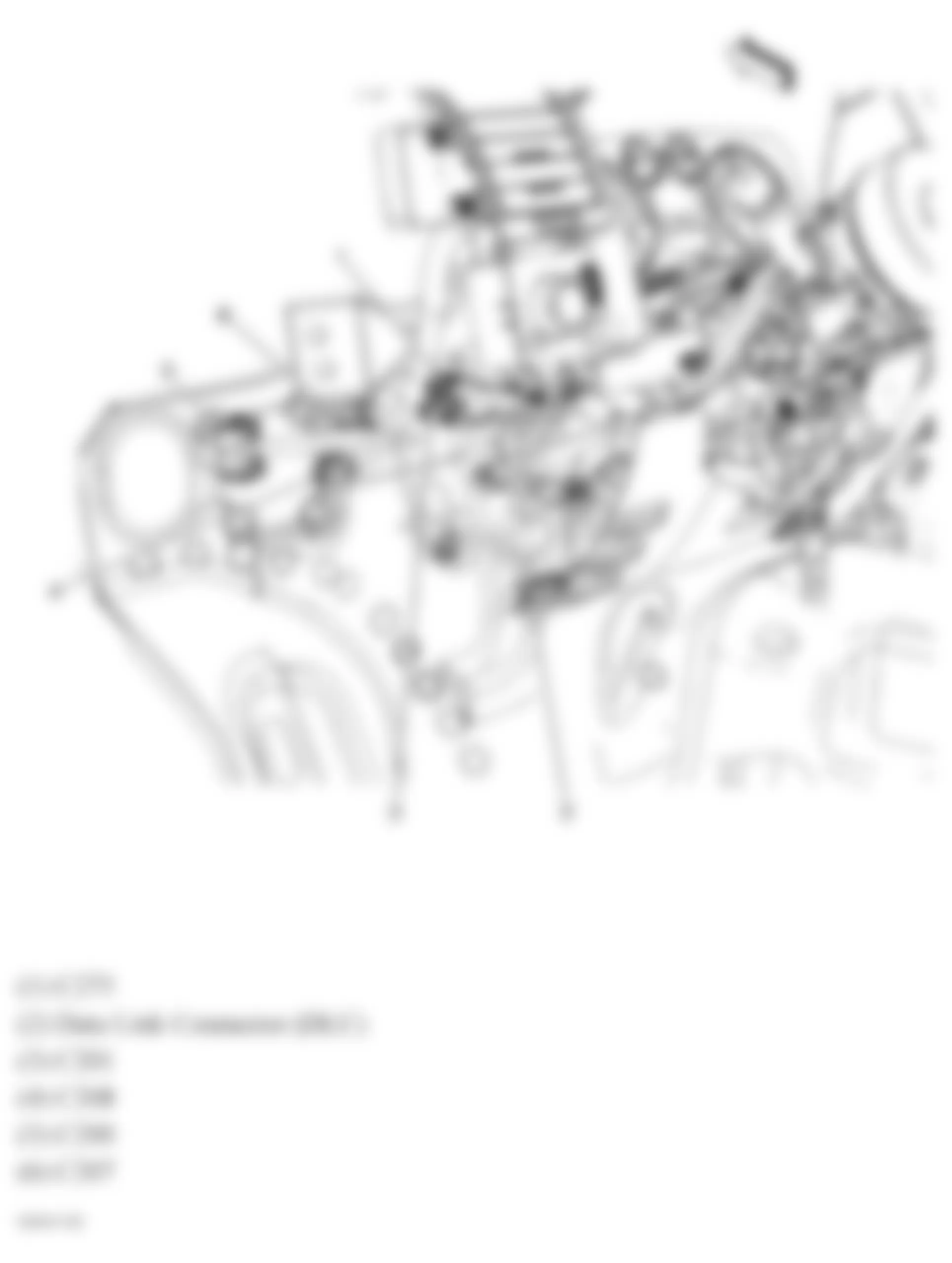
Fig. 52: Hummer H3 2007 - Component Locations - Right Side Of Dash
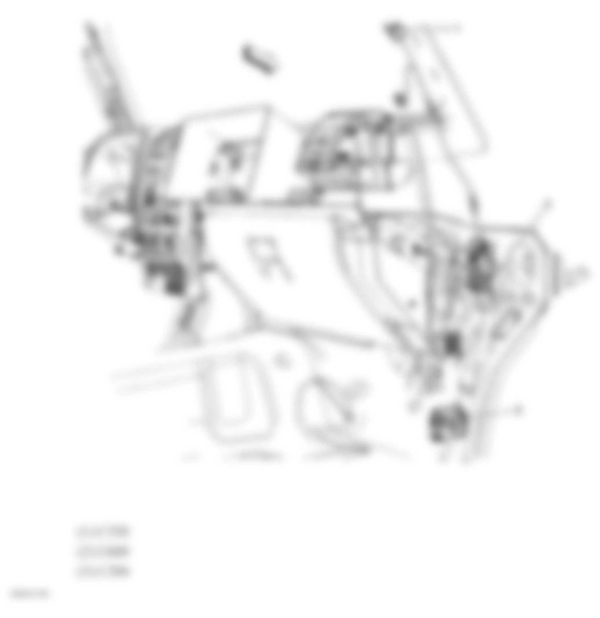
Fig. 53: Hummer H3 2007 - Component Locations - Passenger Compartment
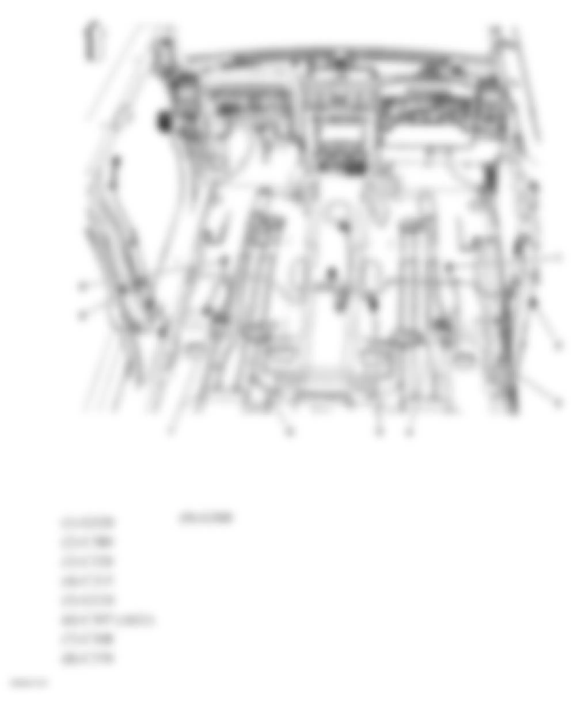
Fig. 54: Hummer H3 2007 - Component Locations - Rear Compartment Area
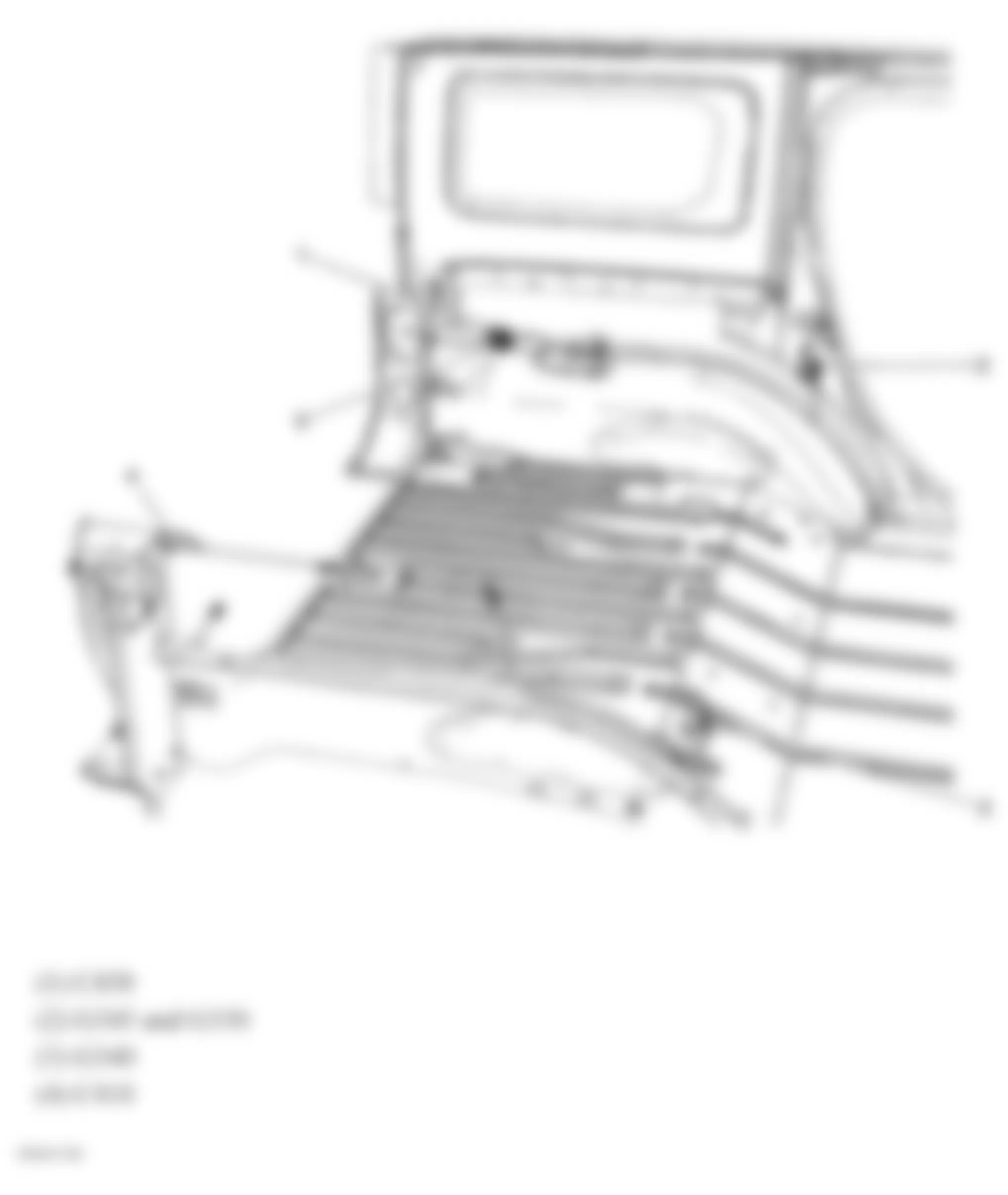
Fig. 55: Hummer H3 2007 - Component Locations - Trailer Hitch Harness
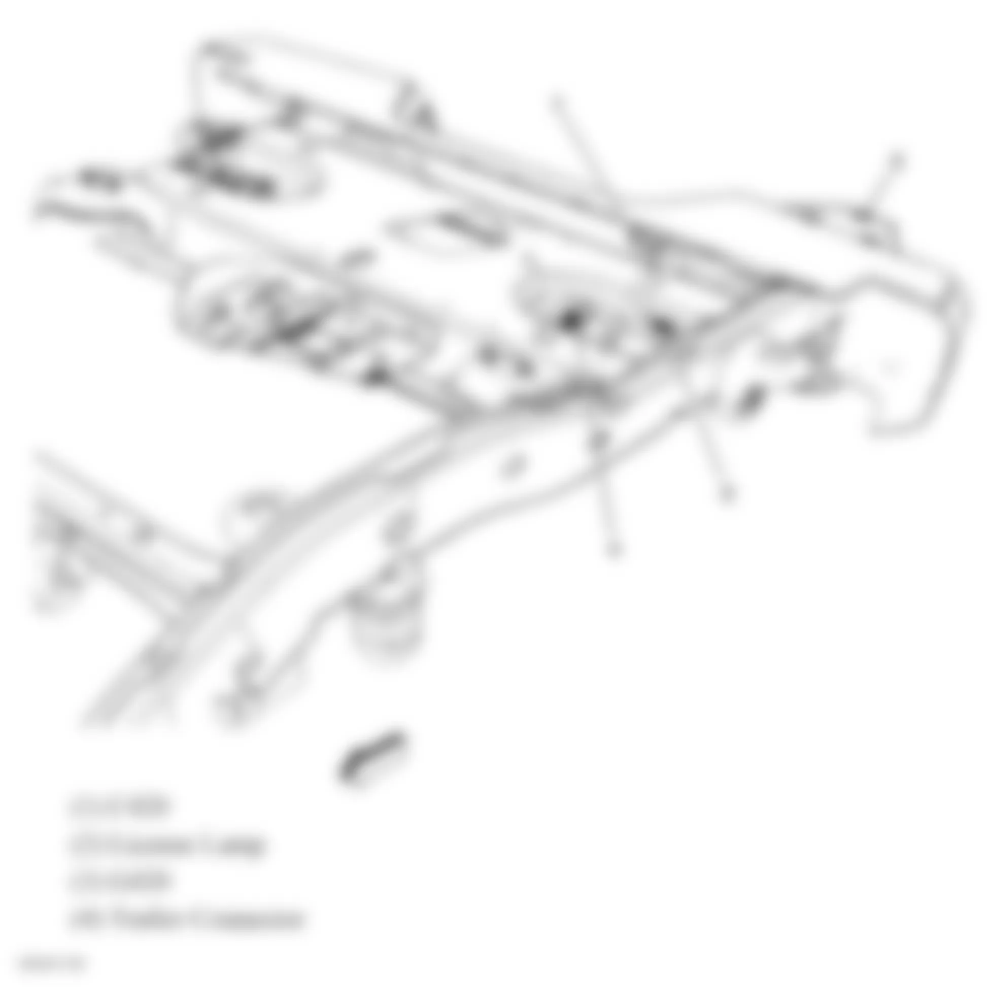
Fig. 56: Hummer H3 2007 - Component Locations - Front Engine Compartment
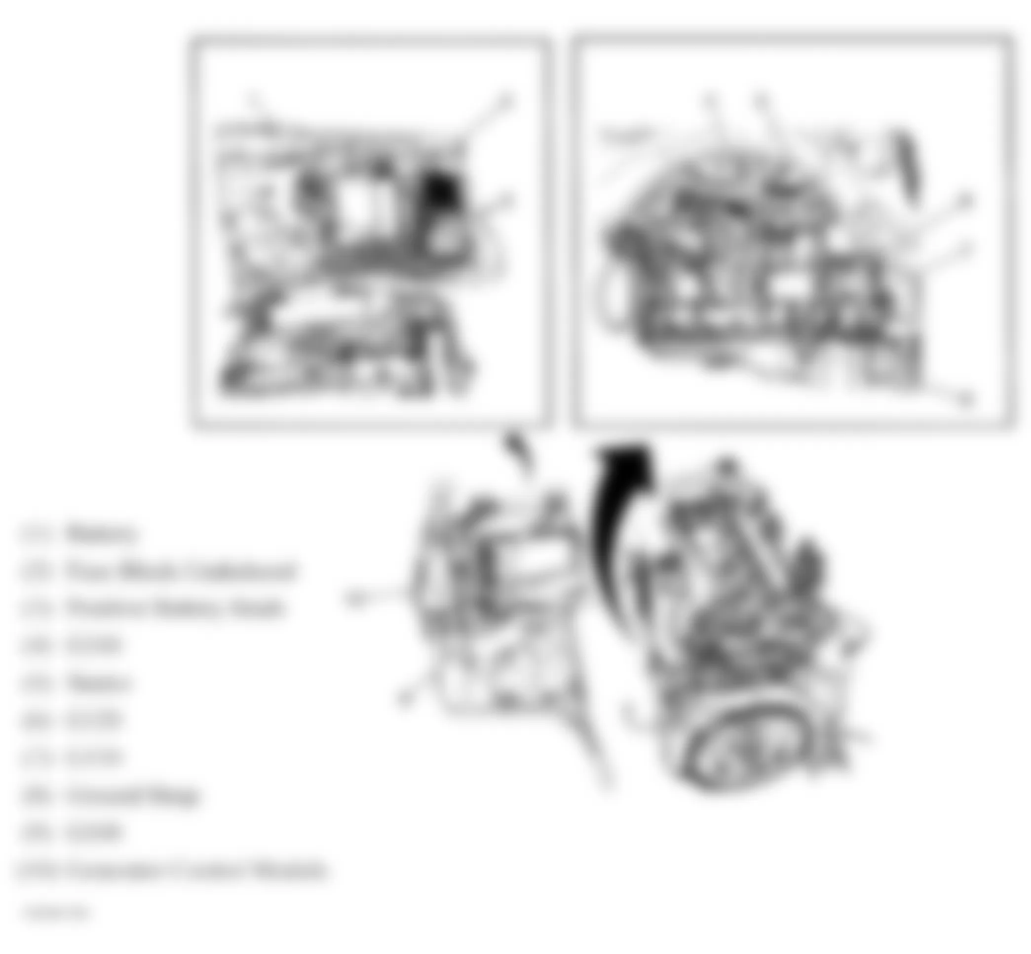
Fig. 57: Hummer H3 2007 - Component Locations - Passenger Compartment Splices
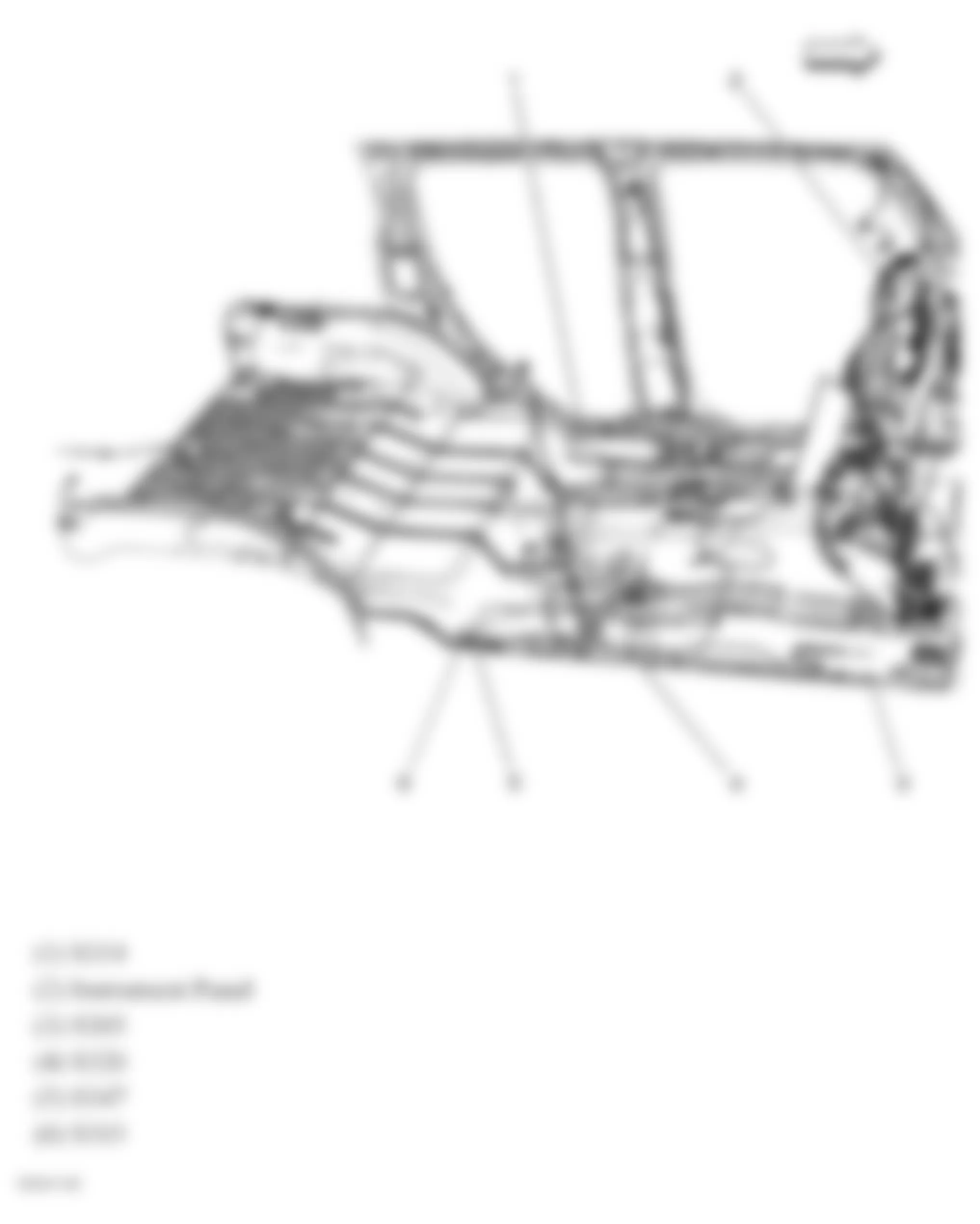
Fig. 58: Hummer H3 2007 - Component Locations - Dash & Passenger Compartment Splices
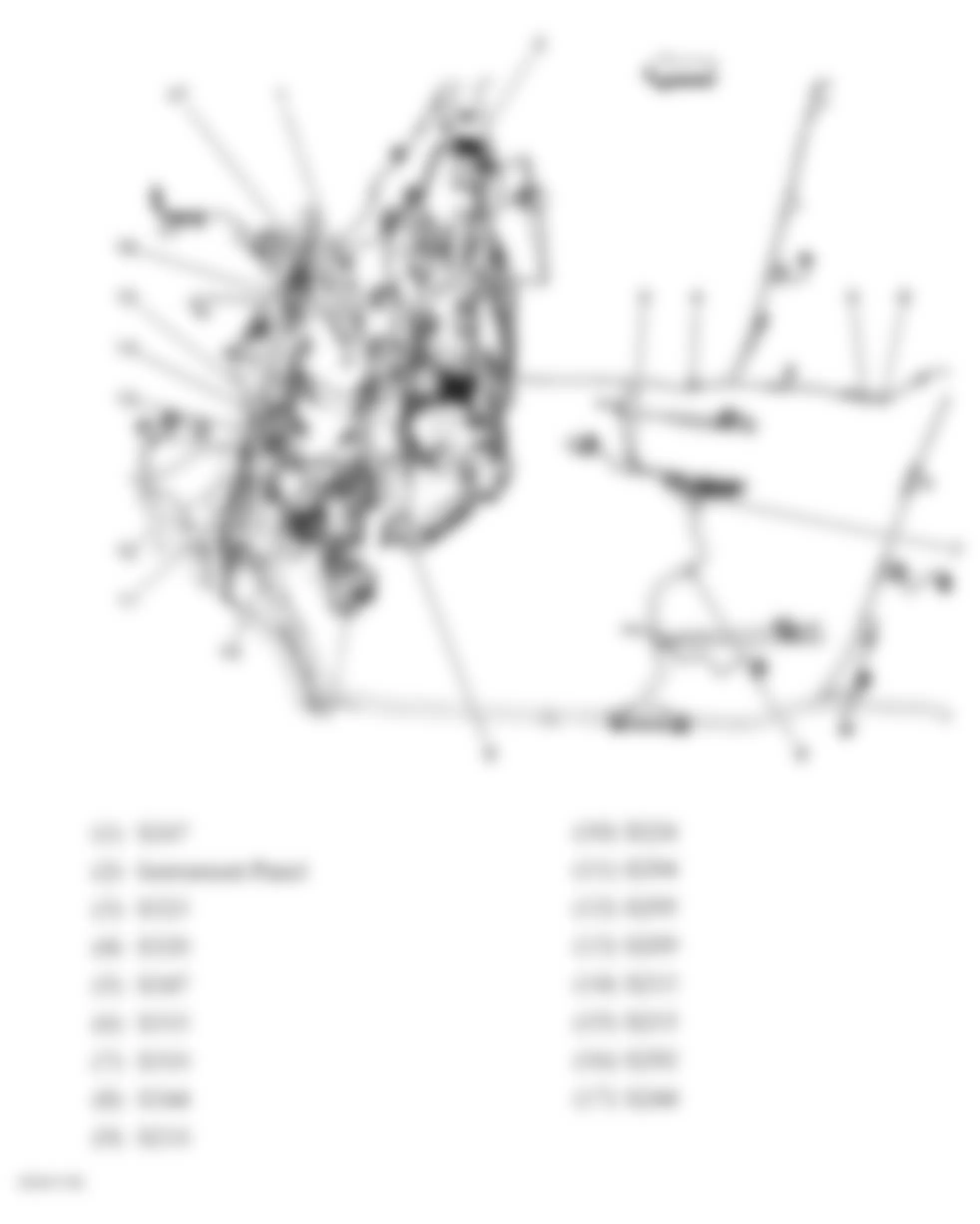
Fig. 59: Hummer H3 2007 - Component Locations - Chassis Harness Routing
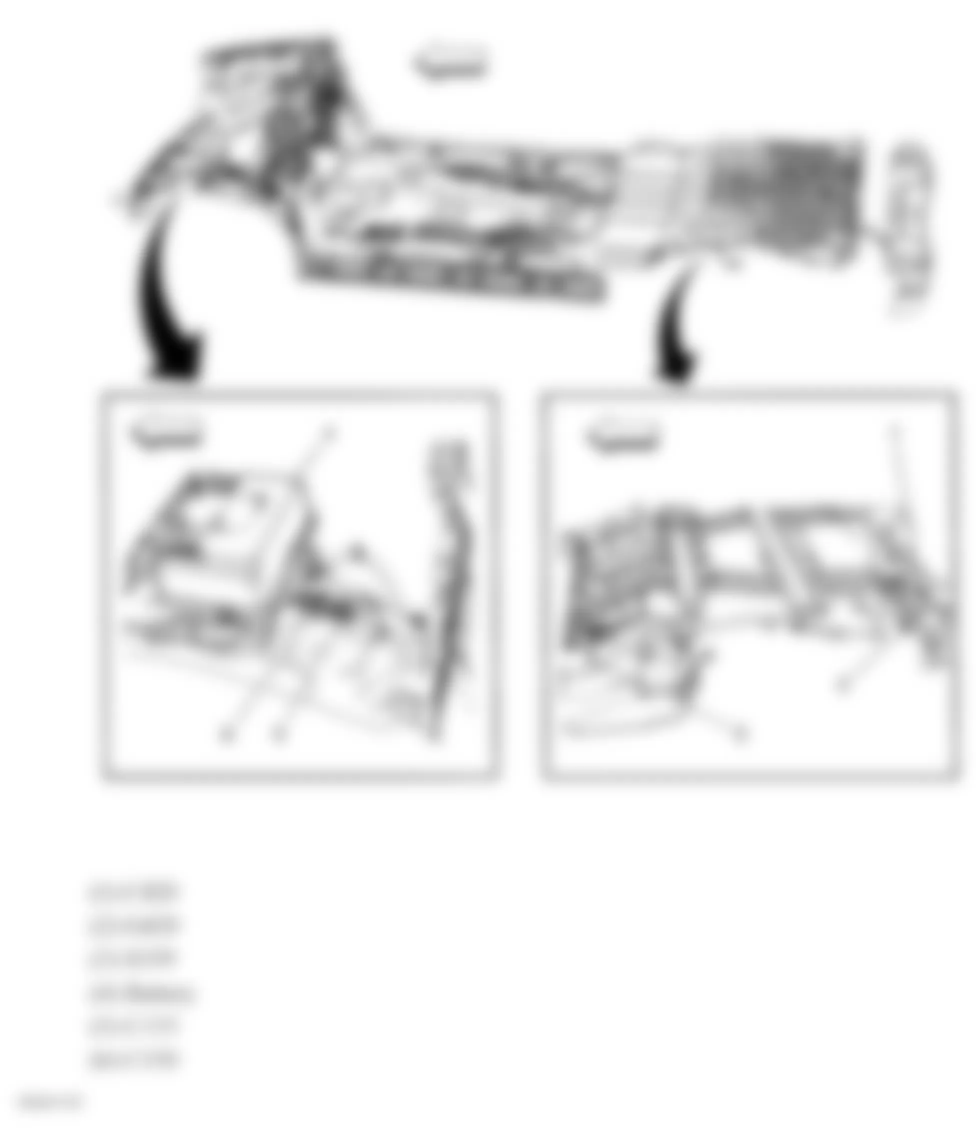
Fig. 60: Hummer H3 2007 - Component Locations - Underhood Fuse Block